
Product Brochure
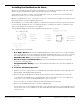
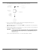
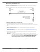
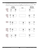
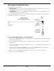
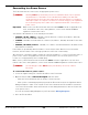
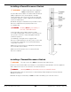
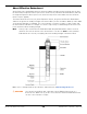
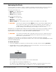
Table Of Contents
- HD-7P and HD-7W Manual
- Table of Contents
- Introduction
- Shipping Information
- Safety Considerations
- Components
- Specifications
- Frequently Asked Questions
- Installation Checklist
- Installation
- Being Safe
- Tools
- Planning for Electrical Work
- Selecting an Approach Direction
- Selecting a Power Post Location
- Checking Clearances
- Selecting a Location
- Unloading and Unpacking
- Creating Chalk Line Guides
- Moving the Posts into Position
- Installing the Crosstubes
- About Safety Locks
- Installing the Ladders and Top Cap
- Raising the Crosstubes
- Securing the Ladders
- Removing Sheaves
- Installing the Runways
- Installing the First End of the Flex Tube
- Routing the Lifting Cables
- Working with Compression Fittings and Tubing
- Installing the Air Lines
- Installing the Hydraulic Hose
- Installing the Return Line
- Installing the Power Unit
- Filling the Hydraulic Fluid Reservoir
- Installing the Second End of the Flex Tube
- Installing the Pushbutton Air Valve
- Connecting the Return Line
- Connecting the Hydraulic Hose
- Contacting the Electrician
- Connecting to a Power Source
- Installing a Power Disconnect Switch
- Installing a Thermal Disconnect Switch
- About Effective Embedment
- Anchoring the Posts
- Final Leveling
- Installing Accessories
- Lubricating the Lift
- Performing an Operational Test
- Reviewing the Final Checklist
- Operation
- Maintenance
- Troubleshooting
- Wiring Diagrams
- Labels
- Parts Drawings
- Automotive Lift Institute (ALI) Store
- Maintenance Log

HD-7P / HD-7W Four-Post Lifts 51 P/N 5900041 — Rev. M — July 2019
Installing the Pushbutton Air Valve
Once the Power Unit and the Flex Tube are installed, you can install the Pushbutton Air Valve, which
requires the Zero Angle Bracket (which may already have been installed).
The Pushbutton Air Valve is used to lower the Runways. It can go on either side of the Power Unit,
whichever is easier to access for the Lift operator.
Once the pushbutton is in place, you need to connect it to both the Air Line (which is coming out of the
Flex Tube) and the customer-supplied air pressure.
An Air Supply (3 to 25 cfm at 50 to 150 psi) is required to disengage the Safety Locks when you want
to lower the Lift. Regulate the line to a maximum pressure of 150 psi; the air lines could burst or the
Safety Locks malfunction at pressure over 150 psi.
The following drawing shows the Zero Angle Bracket and where it connects.
The components involved include:
• Zero Angle Bracket. Attaches at the Mounting Bracket on the Power Post or to other available
holes on the Back Plate of the Power Unit. Holds the Pushbutton Air Valve, so be sure to orient the
Zero Angle Bracket so that the Pushbutton Air Valve can be easily reached by the Lift operator.
• Pushbutton Air Valve. Used to lower the Runways.
• Air Line Compression Elbow Fitting. Connects the Pushbutton Air Valve to the Air Line
coming out of the Flex Tube.
• Straight Expander Fitting. Connects the Pushbutton Air Valve to the customer-supplied air
pressure.
To install the Pushbutton Air Valve:
1. Find the necessary components: Zero Angle Bracket, Pushbutton Air Valve, Air Line Compression
Elbow Fitting, and Straight Expander Fitting.
2. Connect the Zero Angle Bracket at the desired location (if it has not already been connected).
It can attach to an available hole on the Back Plate of the Power Unit or to one of the Bolts that
connect the Power Unit to the Mounting Bracket on the Power Post.
The best location is one that is visible and easily reached by the Lift operator.
3. Connect the Pushbutton Air Valve to the Zero Angle Bracket.
Use the two holes on the Pushbutton Air Valve on the side away from the actual pushbutton. If you
use the holes next to the pushbutton, the Zero Angle Bracket interferes with the pushbutton when
you try to use it.