
Product Brochure
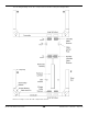
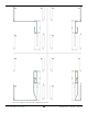
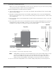
Table Of Contents
- HD-7P and HD-7W Manual
- Table of Contents
- Introduction
- Shipping Information
- Safety Considerations
- Components
- Specifications
- Frequently Asked Questions
- Installation Checklist
- Installation
- Being Safe
- Tools
- Planning for Electrical Work
- Selecting an Approach Direction
- Selecting a Power Post Location
- Checking Clearances
- Selecting a Location
- Unloading and Unpacking
- Creating Chalk Line Guides
- Moving the Posts into Position
- Installing the Crosstubes
- About Safety Locks
- Installing the Ladders and Top Cap
- Raising the Crosstubes
- Securing the Ladders
- Removing Sheaves
- Installing the Runways
- Installing the First End of the Flex Tube
- Routing the Lifting Cables
- Working with Compression Fittings and Tubing
- Installing the Air Lines
- Installing the Hydraulic Hose
- Installing the Return Line
- Installing the Power Unit
- Filling the Hydraulic Fluid Reservoir
- Installing the Second End of the Flex Tube
- Installing the Pushbutton Air Valve
- Connecting the Return Line
- Connecting the Hydraulic Hose
- Contacting the Electrician
- Connecting to a Power Source
- Installing a Power Disconnect Switch
- Installing a Thermal Disconnect Switch
- About Effective Embedment
- Anchoring the Posts
- Final Leveling
- Installing Accessories
- Lubricating the Lift
- Performing an Operational Test
- Reviewing the Final Checklist
- Operation
- Maintenance
- Troubleshooting
- Wiring Diagrams
- Labels
- Parts Drawings
- Automotive Lift Institute (ALI) Store
- Maintenance Log

HD-7P / HD-7W Four-Post Lifts 40 P/N 5900041 — Rev. M — July 2019
Routing Lifting Cables B and D is the same process as routing Lifting Cables A and C, just to the other
two Posts and using a different set of Sheaves. Refer to the drawings in the previous section.
To route Lifting Cables B and D:
1.
Starting with Lifting Cable B
, move it to just under the Large Window it goes through, near
the bottom of Post B.
Check the label to make sure you have the correct Lifting Cable.
2. Remove the Nut and Washer from the Threaded End.
3. Route the Threaded End of Lifting Cable B into its Large Window on the Crosstube, push it toward
the Power Post, then pull the Threaded End out of the Crosstube at the bottom of the Gusset.
You can access the Large Window on the Crosstube because the double Cable Sheave has been
removed. If it is not removed, it blocks access to the Large Window.
4. Route the Threaded End of Lifting Cable B
under
where the Gusset Sheave will go when it is
reinstalled, then route it up towards the top of the Post past the top of the Crosstube Gusset.
When you start routing the Cable up, it
must
be between the Gusset Sheave and the Slack Safety
Sheave, as shown in the drawing above.
Important: When routing a Lifting Cable in its Post, it must go
under
where the Gusset
Sheave will go when the Gusset Sheave is reinstalled and then, when it heads up
towards the top of the Post, it must be between where the Gusset Sheave will go
and where the Slack Safety Sheave already is. If the Cable is
not in this exact
location
, the Slack Safeties will
not
work correctly later on.
5. Reinstall the Gusset Sheave and the Cable Lock Pin in Post B.
6. Double check to make sure Lifting Cable B is correctly positioned: in the Gusset Sheave, between
the Gusset Sheave and the Slack Safety Sheave, with the Cable Lock Pin
under
it.
7. Push the Threaded End of Lifting Cable B up to and through the Top Cap (at the top of the Post)
and
hand tighten
it in place with the Nut and Washer you removed earlier.
You only want to hand tighten the Nut at this point so that there is a little play in the cabling. We
will securely tighten all four Nuts later in the installation procedure.
Note: The Threaded end of Lifting Cable B should go just a little bit through the Top Cap. If it is
way too long or way too short, you probably have the wrong Lifting Cable. If it is just a
few inches short, then the Piston on the Hydraulic Cylinder may not have been pulled out
far enough.
8. Make sure the Button End and the unrouted part of Lifting Cable B is under the Large Window,
near the bottom of Post B.
9.
Switching to Lifting Cable D
, repeat Steps 1 through 6 for Lifting Cable D, starting at the
Small Window near the bottom of Post D.
10. Once the Threaded End of Lifting Cable D is secured at its Top Cap, return to the Small Window at
the bottom of Post D.
11. Under the Powerside Runway, move the rest of Lifting Cable D towards where the Side Sheave
goes on the Post D side of the Runway.
12. Return to the Small Window and reinstall the Cable Sheave.
13. Double check to make sure Lifting Cable D is correctly positioned in the Cable Sheave in the Small
Window.