
Product Brochure
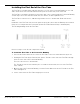
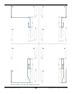
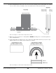
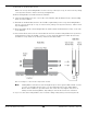
Table Of Contents
- HD-7P and HD-7W Manual
- Table of Contents
- Introduction
- Shipping Information
- Safety Considerations
- Components
- Specifications
- Frequently Asked Questions
- Installation Checklist
- Installation
- Being Safe
- Tools
- Planning for Electrical Work
- Selecting an Approach Direction
- Selecting a Power Post Location
- Checking Clearances
- Selecting a Location
- Unloading and Unpacking
- Creating Chalk Line Guides
- Moving the Posts into Position
- Installing the Crosstubes
- About Safety Locks
- Installing the Ladders and Top Cap
- Raising the Crosstubes
- Securing the Ladders
- Removing Sheaves
- Installing the Runways
- Installing the First End of the Flex Tube
- Routing the Lifting Cables
- Working with Compression Fittings and Tubing
- Installing the Air Lines
- Installing the Hydraulic Hose
- Installing the Return Line
- Installing the Power Unit
- Filling the Hydraulic Fluid Reservoir
- Installing the Second End of the Flex Tube
- Installing the Pushbutton Air Valve
- Connecting the Return Line
- Connecting the Hydraulic Hose
- Contacting the Electrician
- Connecting to a Power Source
- Installing a Power Disconnect Switch
- Installing a Thermal Disconnect Switch
- About Effective Embedment
- Anchoring the Posts
- Final Leveling
- Installing Accessories
- Lubricating the Lift
- Performing an Operational Test
- Reviewing the Final Checklist
- Operation
- Maintenance
- Troubleshooting
- Wiring Diagrams
- Labels
- Parts Drawings
- Automotive Lift Institute (ALI) Store
- Maintenance Log

HD-7P / HD-7W Four-Post Lifts 32 P/N 5900041 — Rev. M — July 2019
Installing the First End of the Flex Tube
The Flex Tube is a flexible, black tube that attaches to a hole on the Powerside Runway on one end
and to the bottom of the Flex Tube Bracket Plate (near the Power Unit) on the other end.
The Flex Tube consolidates and protects three lines that come out from under the Powerside Runway
on their way to the Power Unit: the Return Line, the Air Line, and the Hydraulic Hose.
The Flex Tube is about 52 in / 1,320 mm long and about 1.5 in / 38 mm wide. Both ends are the
same.
Installation of the Flex Tube is done in two parts: the first part is done after the Runways are installed
(now), the second part after the Power Unit (and the Flex Tube Bracket Plate) is installed (later).
The following drawing shows the Flex Tube.
Not necessarily to scale. Not all components shown.
To install the Flex Tube to the Powerside Runway:
1. Unscrew the Plastic Nut from one end of the Flex Tube. It does not matter which end you use.
2. Holding the Flex Tube by the Plastic Collar, put the Threads on the end of the Flex Tube through
the hole on the side of the Powerside Runway.
The hole is about 1.5 in / 38 mm wide.
The Threads go into the hole until they are accessible from the inside, the rest of the Flex Tube
stays outside.
3. On the inside of the Powerside Runway, screw the Plastic Nut back onto the Threads of the Flex
Tube and tighten it.
4. Let the other end of the Flex Tube hang in place for now.