
Product Brochure
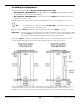
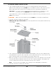
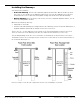
Table Of Contents
- HD-7P and HD-7W Manual
- Table of Contents
- Introduction
- Shipping Information
- Safety Considerations
- Components
- Specifications
- Frequently Asked Questions
- Installation Checklist
- Installation
- Being Safe
- Tools
- Planning for Electrical Work
- Selecting an Approach Direction
- Selecting a Power Post Location
- Checking Clearances
- Selecting a Location
- Unloading and Unpacking
- Creating Chalk Line Guides
- Moving the Posts into Position
- Installing the Crosstubes
- About Safety Locks
- Installing the Ladders and Top Cap
- Raising the Crosstubes
- Securing the Ladders
- Removing Sheaves
- Installing the Runways
- Installing the First End of the Flex Tube
- Routing the Lifting Cables
- Working with Compression Fittings and Tubing
- Installing the Air Lines
- Installing the Hydraulic Hose
- Installing the Return Line
- Installing the Power Unit
- Filling the Hydraulic Fluid Reservoir
- Installing the Second End of the Flex Tube
- Installing the Pushbutton Air Valve
- Connecting the Return Line
- Connecting the Hydraulic Hose
- Contacting the Electrician
- Connecting to a Power Source
- Installing a Power Disconnect Switch
- Installing a Thermal Disconnect Switch
- About Effective Embedment
- Anchoring the Posts
- Final Leveling
- Installing Accessories
- Lubricating the Lift
- Performing an Operational Test
- Reviewing the Final Checklist
- Operation
- Maintenance
- Troubleshooting
- Wiring Diagrams
- Labels
- Parts Drawings
- Automotive Lift Institute (ALI) Store
- Maintenance Log

HD-7P / HD-7W Four-Post Lifts 30 P/N 5900041 — Rev. M — July 2019
Installing the Runways
Your Lift has two Runways:
• Powerside Runway: Has the Lift’s Hydraulic Cylinder underneath it. Gets bolted into position.
Has a hole on the outside (on the Cylinder end) that lets you route the Hydraulic Hose, Air Lines,
and Return Line to the Power Unit. Lifting Cable routing ends under the Powerside Runway.
• Offside Runway: Gets bolted into position. Does not have a Hydraulic Cylinder under it, nor are
there any Lifting Cables under it.
Orient the two Runways this way:
• Utility Rails on the inside
• Find the Powerside Runway by looking under the two Runways (only the Powerside Runway has a
Hydraulic Cylinder underneath it) and put it next to the Power Post.
There is also an ~1.5 inch wide hole in the outside of the Powerside Runway near the Power Post.
There are other holes in the Runways, but they are smaller and used with accessories only.
The following drawing shows the correct orientation of the Runways for both Power Post locations.
The Ramp locations do not change based on Power Post location, but the location and orientation of
the Powerside Runway does.
Not necessarily to scale. Not all components shown. Tops of Runways not shown.