
Product Brochure
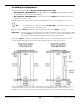
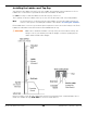
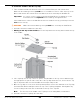
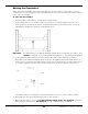
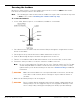
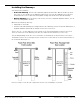
Table Of Contents
- HD-7P and HD-7W Manual
- Table of Contents
- Introduction
- Shipping Information
- Safety Considerations
- Components
- Specifications
- Frequently Asked Questions
- Installation Checklist
- Installation
- Being Safe
- Tools
- Planning for Electrical Work
- Selecting an Approach Direction
- Selecting a Power Post Location
- Checking Clearances
- Selecting a Location
- Unloading and Unpacking
- Creating Chalk Line Guides
- Moving the Posts into Position
- Installing the Crosstubes
- About Safety Locks
- Installing the Ladders and Top Cap
- Raising the Crosstubes
- Securing the Ladders
- Removing Sheaves
- Installing the Runways
- Installing the First End of the Flex Tube
- Routing the Lifting Cables
- Working with Compression Fittings and Tubing
- Installing the Air Lines
- Installing the Hydraulic Hose
- Installing the Return Line
- Installing the Power Unit
- Filling the Hydraulic Fluid Reservoir
- Installing the Second End of the Flex Tube
- Installing the Pushbutton Air Valve
- Connecting the Return Line
- Connecting the Hydraulic Hose
- Contacting the Electrician
- Connecting to a Power Source
- Installing a Power Disconnect Switch
- Installing a Thermal Disconnect Switch
- About Effective Embedment
- Anchoring the Posts
- Final Leveling
- Installing Accessories
- Lubricating the Lift
- Performing an Operational Test
- Reviewing the Final Checklist
- Operation
- Maintenance
- Troubleshooting
- Wiring Diagrams
- Labels
- Parts Drawings
- Automotive Lift Institute (ALI) Store
- Maintenance Log

HD-7P / HD-7W Four-Post Lifts 27 P/N 5900041 — Rev. M — July 2019
Raising the Crosstubes
At this point in the installation you need to manually raise the Crosstubes, as this makes it easier to
complete the rest of the installation tasks. Both Crosstubes need to be raised the exact same amount,
to the exact same height.
To raise the Crosstubes:
1. Using a Forklift or Shop Crane, carefully raise each Crosstube.
You probably want to raise the Crosstubes at least two feet off the ground, but it is up to you.
Some people move them up enough to work under them, which can make it easier to route the
Lifting Cables, Return Line, Air Lines, and Hydraulic Hose.
Important: The Slack Safety Locks will automatically engage when you raise the Crosstubes. They
cannot
be engaged as you continue with the installation, so they must be disengaged.
2. To disengage the Slack Safety Locks after raising a Crosstube: raise and hold one end of a
Crosstube so the Primary and Slack Safety Locks are disengaged, push and hold the Sheave or
the Steel Piece in towards the Ladder and the back of the Post (this moves the Slack Safety Lock
so it cannot engage), lower the end of the Crosstube, then release the Sheave or Steel Piece.
The Primary Safety Lock engages, but the Slack Safety Lock does not; this is what you want.
3. Disengage the other three Slack Safety Locks as done in Step 2.
4. Once both Crosstubes are raised,
all four Primary Safety Locks are engaged
, and all four
Slack Safety Locks have been disengaged, you can continue with the installation.