
Product Brochure
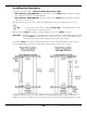
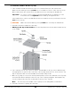
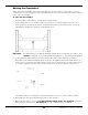
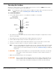
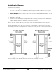
Table Of Contents
- HD-7P and HD-7W Manual
- Table of Contents
- Introduction
- Shipping Information
- Safety Considerations
- Components
- Specifications
- Frequently Asked Questions
- Installation Checklist
- Installation
- Being Safe
- Tools
- Planning for Electrical Work
- Selecting an Approach Direction
- Selecting a Power Post Location
- Checking Clearances
- Selecting a Location
- Unloading and Unpacking
- Creating Chalk Line Guides
- Moving the Posts into Position
- Installing the Crosstubes
- About Safety Locks
- Installing the Ladders and Top Cap
- Raising the Crosstubes
- Securing the Ladders
- Removing Sheaves
- Installing the Runways
- Installing the First End of the Flex Tube
- Routing the Lifting Cables
- Working with Compression Fittings and Tubing
- Installing the Air Lines
- Installing the Hydraulic Hose
- Installing the Return Line
- Installing the Power Unit
- Filling the Hydraulic Fluid Reservoir
- Installing the Second End of the Flex Tube
- Installing the Pushbutton Air Valve
- Connecting the Return Line
- Connecting the Hydraulic Hose
- Contacting the Electrician
- Connecting to a Power Source
- Installing a Power Disconnect Switch
- Installing a Thermal Disconnect Switch
- About Effective Embedment
- Anchoring the Posts
- Final Leveling
- Installing Accessories
- Lubricating the Lift
- Performing an Operational Test
- Reviewing the Final Checklist
- Operation
- Maintenance
- Troubleshooting
- Wiring Diagrams
- Labels
- Parts Drawings
- Automotive Lift Institute (ALI) Store
- Maintenance Log

HD-7P / HD-7W Four-Post Lifts 23 P/N 5900041 — Rev. M — July 2019
To install the Crosstubes:
1. Orient the Crosstubes in their
required
locations:
• The Crosstube with two Large Windows must be on the Pull Box end of the Powerside
Runway with both Windows facing the inside of the Lift.
• The Crosstube with two Small Windows must be located next to the Power Post with both
Windows facing the inside of the Lift.
Both Windows must be on the ends of the Powerside Runway and facing the inside of the Lift.
2. Lean over the
two
Posts at one end of the Lift (some people put them on Sawhorses, some
people let them lay on the ground), slide the Crosstube into place, then stand the Posts back up
again (make sure to put them back into their correct locations).
or
Using a Forklift or Shop Crane, raise a Crosstube above the top of the two Posts that it goes
between, then slide the Crosstube down into place.
3. Perform Step 2 for the second Crosstube.
About Slide Blocks
The black Slide Blocks in the corners of the ends of the Crosstubes come installed from the factory. If
they fall off or do not come installed, put them into place so that each pair creates a Slot into which the
Ladder for each Post will be installed later in the installation procedure.
The following drawing is a top view of how two Slide Blocks get put into position on the end of a
Crosstube.
The following drawing is a top view that shows the Slot created by the two Slide Blocks when they are
installed. There are two Slots per Crosstube Gusset, one at the top and one at the bottom. The Ladder
must
go through
both
Slots.
Important: It is easy to see the top Slot created by the Slide Blocks. It is difficult to see the bottom
Slot, but it is
required
that the Ladder go through
both
Slots.