
Product Brochure
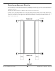
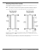
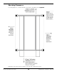
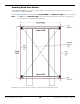
Table Of Contents
- HD-7P and HD-7W Manual
- Table of Contents
- Introduction
- Shipping Information
- Safety Considerations
- Components
- Specifications
- Frequently Asked Questions
- Installation Checklist
- Installation
- Being Safe
- Tools
- Planning for Electrical Work
- Selecting an Approach Direction
- Selecting a Power Post Location
- Checking Clearances
- Selecting a Location
- Unloading and Unpacking
- Creating Chalk Line Guides
- Moving the Posts into Position
- Installing the Crosstubes
- About Safety Locks
- Installing the Ladders and Top Cap
- Raising the Crosstubes
- Securing the Ladders
- Removing Sheaves
- Installing the Runways
- Installing the First End of the Flex Tube
- Routing the Lifting Cables
- Working with Compression Fittings and Tubing
- Installing the Air Lines
- Installing the Hydraulic Hose
- Installing the Return Line
- Installing the Power Unit
- Filling the Hydraulic Fluid Reservoir
- Installing the Second End of the Flex Tube
- Installing the Pushbutton Air Valve
- Connecting the Return Line
- Connecting the Hydraulic Hose
- Contacting the Electrician
- Connecting to a Power Source
- Installing a Power Disconnect Switch
- Installing a Thermal Disconnect Switch
- About Effective Embedment
- Anchoring the Posts
- Final Leveling
- Installing Accessories
- Lubricating the Lift
- Performing an Operational Test
- Reviewing the Final Checklist
- Operation
- Maintenance
- Troubleshooting
- Wiring Diagrams
- Labels
- Parts Drawings
- Automotive Lift Institute (ALI) Store
- Maintenance Log

HD-7P / HD-7W Four-Post Lifts 20 P/N 5900041 — Rev. M — July 2019
To create Chalk Line Guides:
1. Create the Front Chalk Line where you want the Front of the Lift.
The Front of the Lift is the end opposite the Ramps.
Make the Front Chalk Line longer, by 12 inches on each end, than the Overall Width setting.
2. Create the two side Chalk Lines at 90° angles to the Front Chalk Line and parallel to each other.
Make the side Chalk Lines longer (by 12 inches on each end) than the Outside Length setting.
The side Chalk Lines
must
be parallel to each other.
Measure to verify that they are parallel.
3. Create the Rear Chalk Line parallel to the Front Chalk Line. Make the Rear Chalk Line longer than
the Overall Width setting for your Lift model.
The Front and Rear Chalk Lines
must
also be parallel to each other.
Measure to verify that they are parallel.
4. Before moving the Posts into position, measure
diagonally
to make sure the two diagonal
measurements are the same. This ensures your layout is correct.
Do not forget to check the diagonals.
5. When you move the Posts into position, put the outside edges of the bases inside the corners
created by the Chalk Line Guides.