645 Lemonwood Dr. Santa Paula, CA 93060 USA Toll Free: (800) 253-2363 Telephone: (805) 933-9970 bendpak.com Four-Post Lifts Installation and Operation Manual Manual P/N 5900041 — Manual Revision M — July 2019 Models: • HD-7P • HD-7W Designed and engineered by BendPak Inc. in Southern California, USA. Made in China. ⚠ DANGER Read the entire contents of this manual before using this product. Failure to follow the instructions and safety precautions in this manual can result in serious injury or death.
Manual. HD-7P and HD-7W Four-Post Lifts, Installation and Operation Manual, Manual P/N 5900041, Manual Revision M, Released July 2019. Copyright. Copyright © 2019 by BendPak Inc. All rights reserved. You may make copies of this document if you agree that: you will give full attribution to BendPak Inc., you will not make changes to the content, you do not gain any rights to this content, and you will not use the copies for commercial purposes. Trademarks.
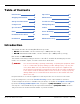
Table of Contents Introduction 3 Operation 69 Shipping Information 4 Maintenance 73 Safety Considerations 4 Troubleshooting 75 Components 6 Wiring Diagrams 77 Specifications 8 Labels 79 FAQs 10 Parts Drawings 82 Installation Checklist 11 ALI Store 90 Installation 12 Maintenance Log 91 Introduction This manual describes the following BendPak four-post Lifts: • HD-7P: Standard width, can raise Vehicles up to 7,000 pounds (3,175 kg).
Shipping Information Your equipment was carefully checked before shipping. Nevertheless, you should thoroughly inspect the shipment before you sign to acknowledge that you received it. When you sign a bill of lading, it tells the carrier that the items on the invoice were received in good condition. To protect yourself, do not sign until after you have inspected the shipment.
Symbols Following are the symbols used in this manual: ⚠ DANGER ⚠ WARNING ⚠ CAUTION NOTICE Tip Calls attention to an immediate hazard that will result in death or severe injury. Calls attention to a hazard or unsafe practice that could result in death or severe personal injury. Calls attention to a hazard or unsafe practice that could result in minor personal injury, product damage, or property damage. Calls attention to a situation that, if not avoided, could result in product or property damage.
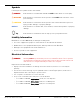
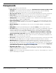
Components The main components of your Lift include: • • • • • • • • • • • Power Post. The Post that holds the Power Unit. The Power Post can be in either of two locations. You can tell the Power Post from the other Posts because it has two Mounting Brackets on it. Mount the Power Unit on one of the two Mounting Brackets. The other three Posts. These Posts are functionally interchangeable; their Labels are different. Power Unit.
Drawing not necessarily to scale. Some components not shown. Crosstube Windows for the Crosstube on the left not visible in this view. Accessories • • • • Rolling Jack(s). Optional product that raises wheels of the Vehicle on the Lift off the Runway, making it much easier to perform certain jobs while the Vehicle is still on the Lift. Refer to the Rolling Jack page on the BendPak website for more information. Air Line Kit.
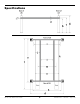
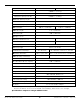
Specifications HD-7P / HD-7W Four-Post Lifts 8 P/N 5900041 — Rev.
Model HD-7P Lifting capacity 7,000 lbs / 3,175 kg Maximum capacity front axle 3,500 lbs / 1,750 kg Maximum capacity rear axle 3,500 lbs / 1,750 kg a Minimum Runway Height 4.5" / 114 mm b Maximum Rise 82"/ 2,083 mm c Maximum Lifting Height 87" / 2,208 mm d Overall Width 100.25" / 2,546 mm 110.25" / 2,800 mm e Outside Length 174" / 4,418 mm f Overall Length 200" / 5,078 mm g Height of Posts 100" / 2,537 mm h Distance Between Posts 90.25" / 2,292 mm 100.
Frequently Asked Questions Question: Answer: What kinds of Vehicles can I put on my Lift? Cars, trucks, SUVs; anything that fits on the Runways, up to 7,000 lbs (3,175 kg). Q: How long does it take to raise or lower my Lift with a Vehicle on it? A: About 35 seconds. Longer if there is no weight on it. Q: Does the Lift have a Front and a Rear? A: Yes. For a four-post Lift, the end opposite the Ramps is the Front; the end with the Ramps is the Rear.
Installation Checklist Following are the steps needed to install your Lift. Perform them in the order shown. ☐ 1. Review the Safety Rules. ☐ 2. Make sure you have the necessary Tools. ☐ 3. Plan for electrical work. ☐ 4. Select an Approach. ☐ 5. Choose a Power Post Location. ☐ 6. Check the Clearances. ☐ 7. Select the Installation Location. ☐ 8. Unload and unpack the Lift Components. ☐ 9. Create Chalk Line Guides. ☐ 10. Move the Posts into position. ☐ 11. Install the Crosstubes. ☐ 12. About Safety Locks.
Installation The installation process takes multiple steps. Perform them in the order listed. Read the entire Installation section before beginning the install; this gives you a better understanding of the process as a whole. ⚠ WARNING Only use the factory-supplied parts that came with your Lift. If you use parts from a different source, you void your warranty and compromise the safety of everyone who installs or uses the Lift. If you are missing parts, visit bendpak.
Planning for Electrical Work You will need to have a licensed, certified Electrician available at some point during the installation. ⚠ DANGER All electrical work must be performed by a licensed, certified Electrician. Notify your Electrician in advance so that they come prepared with appropriate components for connecting to the power source, a Power Disconnect Switch, and a Thermal Disconnect Switch. Refer to Contacting the Electrician for more information.
Selecting an Approach Direction You need to pick an Approach, the direction you will drive Vehicles onto your Lift, near the beginning of the installation process. It determines where your Ramps and Tire Stops go on the Lift and the Front and Rear of the Lift. Selecting an Approach does not impact your Power Post location choice. In many cases, selecting an Approach is easy: the garage/shop has walls on three sides and an open door on the fourth side. The open door is the Approach side.
Selecting a Power Post Location You need to pick a Power Post location now, near the beginning of the installation process, as its location impacts other aspects of the installation. Note: The Power Post location decision has no impact on the Approach direction or where the Front and Rear of the Lift are. It does impact other aspects of the installation, however. You have two options for Power Post location: Driver-Side Front or Passenger-Side Rear. Drawing not necessarily to scale.
Checking Clearances For safety purposes, a certain amount of clear space around the Lift is required. Drawing is a top view. Not necessarily to scale. Not all components shown. HD-7P / HD-7W Four-Post Lifts 16 P/N 5900041 — Rev.
Selecting a Location When selecting the location for your Lift, consider: • • • • • • • Architectural plans. Consult the architectural plans for your desired installation location. Make sure there are no issues between what you want to do and what the plans show. Available space. Make sure there is enough space for the Lift: front, back, sides, and above. Refer to Specifications for measurements. Overhead obstructions.
Unloading and Unpacking Try to have the components of the Lift unloaded near the installation location. Once the components are unloaded, they are your responsibility to move around. As the Lift includes a number of heavy pieces, the closer you unload them to the installation location, the better off you are. ⚠ CAUTION ⚠ WARNING HD-7P / HD-7W Four-Post Lifts Some Lift components are very heavy; if handled incorrectly, they can damage materials like tile, sandstone, and brick.
Creating Chalk Line Guides Create Chalk Line Guides so that the outside edges of all four Post bases fit into the four corners created by the Chalk Line Guides. Refer to Specifications to determine the Overall Width and Outside Length values for your Lift. Note: Do not use the Overall Length value; this includes the Ramps, which are not taken into consideration for creating Chalk Line Guides. Drawing is a top view. Not necessarily to scale. Not all components shown.
To create Chalk Line Guides: 1. Create the Front Chalk Line where you want the Front of the Lift. The Front of the Lift is the end opposite the Ramps. Make the Front Chalk Line longer, by 12 inches on each end, than the Overall Width setting. 2. Create the two side Chalk Lines at 90° angles to the Front Chalk Line and parallel to each other. Make the side Chalk Lines longer (by 12 inches on each end) than the Outside Length setting. The side Chalk Lines must be parallel to each other.
Moving the Posts into Position Use a Forklift or Shop Crane to move the Posts. You need to have at least two people work together to stand up the Posts. ⚠ DANGER The Posts are heavy and awkward; be very careful when handling them. If they fall on a person, they will cause injury. To move the Posts into position: 1. Using a Forklift or Shop Crane, move the four Posts, one at a time, to the inside corners of the Chalk Line Guides. Important: Position the Power Post at the location you chose earlier.
Installing the Crosstubes Your Lift has two Crosstubes; they are similar, but not the same: • • One with Two Large Windows: This Crosstube has two Large Windows. Must be installed at the Pull Box end of the Powerside Runway. One with Two Small Windows: This Crosstube as two Small Windows. Must be installed adjacent to the Power Post. Both Crosstubes are hollow, which allows the Lifting Cables to be run through them to the Posts.
To install the Crosstubes: 1. Orient the Crosstubes in their required locations: • • The Crosstube with two Large Windows must be on the Pull Box end of the Powerside Runway with both Windows facing the inside of the Lift. The Crosstube with two Small Windows must be located next to the Power Post with both Windows facing the inside of the Lift. Both Windows must be on the ends of the Powerside Runway and facing the inside of the Lift. 2.
About Safety Locks Your Lift has two Safety Lock systems: • • Primary Safety Locks. Located at the ends of each of the four Crosstubes, the Primary Safety Locks hold the Runways in place once they are engaged. Primary Safety Locks are used over 99 percent of the time. Once engaged, Primary Safety Locks hold the Runways in place, even if the power goes out or the Hydraulic Hoses break or leak. Slack Safety Locks.
Installing the Ladders and Top Cap Your Lift has four Ladders (one per Post); each Ladder gets installed on the inside back of a Post. Ladders are secured at the top and the bottom. All four Ladders are identical. It is not necessary to slide the Ladders in from the very top of the Post. The Top Caps secure the Ladder at the top of each Post and hold the ends of the Lifting Cables.
To install the Ladders and the Top Cap: 1. Take a Ladder and slide it down the back of a Post, with the Bolt Hole end at the bottom. Make sure the Ladder goes through both Slots on each Gusset. There is a Slot at the top of the Gusset and another Slot at the bottom of the Gusset; both are formed by the Slide Blocks. Important: It is easy to see the top Slot created by the Slide Blocks. It is difficult to see the bottom Slot, but it is required that the Ladder go through both Slots.
Raising the Crosstubes At this point in the installation you need to manually raise the Crosstubes, as this makes it easier to complete the rest of the installation tasks. Both Crosstubes need to be raised the exact same amount, to the exact same height. To raise the Crosstubes: 1. Using a Forklift or Shop Crane, carefully raise each Crosstube. You probably want to raise the Crosstubes at least two feet off the ground, but it is up to you.
Securing the Ladders Because it is much easier to secure the Ladders at the bottom of each Post after the Crosstubes have been raised, that procedure is described here. Note: The following procedure assumes that the Ladders are in place and secured at the top. If this is not the case, return to Installing the Ladders and Top Cap. To secure the Ladders: 1. Locate a Bolt, Washer, Spacer, second Washer, and Nut for each Ladder. 2.
Removing Sheaves In order to route the Lifting Cables, you need to remove the 10 Cable Sheaves on the underside of the Powerside Runway, the two Side Sheaves, and the four Gusset Sheaves and their Lock Pins. When you remove the Sheaves, keep all of the components together. You will be reinstalling them at the same location, using the same components. Not necessarily to scale. Not all components shown. Combines top and side views. HD-7P / HD-7W Four-Post Lifts 29 P/N 5900041 — Rev.
Installing the Runways Your Lift has two Runways: • • Powerside Runway: Has the Lift’s Hydraulic Cylinder underneath it. Gets bolted into position. Has a hole on the outside (on the Cylinder end) that lets you route the Hydraulic Hose, Air Lines, and Return Line to the Power Unit. Lifting Cable routing ends under the Powerside Runway. Offside Runway: Gets bolted into position. Does not have a Hydraulic Cylinder under it, nor are there any Lifting Cables under it.
Use a Forklift or Shop Crane to raise the Runways and move them into position. ⚠ WARNING Pay close attention when moving the Runways into position; they are heavy and long, and could shift position or fall, potentially causing serious injury. To install the Runways: 1. Correctly orient the Powerside Runway and the Offside Runway. See the previous page for more information. 2. On the underside of the Powerside Runway, make sure the Sheaves have been removed. 3.
Installing the First End of the Flex Tube The Flex Tube is a flexible, black tube that attaches to a hole on the Powerside Runway on one end and to the bottom of the Flex Tube Bracket Plate (near the Power Unit) on the other end. The Flex Tube consolidates and protects three lines that come out from under the Powerside Runway on their way to the Power Unit: the Return Line, the Air Line, and the Hydraulic Hose. The Flex Tube is about 52 in / 1,320 mm long and about 1.5 in / 38 mm wide.
Routing the Lifting Cables Before routing the Lifting Cables, you need to know the following: • • • • • BendPak strongly recommends using gloves when working with the Lifting Cables. Each Lift has four Lifting Cables. All four are different lengths. Each Lifting Cable is the right length for one path. If you use a Lifting Cable in the wrong path, it will be either too short or too long. All Lifting Cables have a Button end and a Threaded end.
The following drawing shows the components involved in routing the Lifting Cables. Not necessarily to scale. Not all components shown. HD-7P / HD-7W Four-Post Lifts 34 P/N 5900041 — Rev.
Not necessarily to scale. Not all components shown. HD-7P / HD-7W Four-Post Lifts 35 P/N 5900041 — Rev.
Before routing your Lifting Cables, you need to extend the Piston of the Hydraulic Cylinder. To extend the Piston: 1. Remove the Shipping Plug from the Return Line Connector. The Return Line Connector is on the Hydraulic Cylinder on the end away from the Pull Box. 2. Attach an air pressure source to the Return Line Connector. 3. Use the air pressure to extend the Hydraulic Cylinder’s Piston and Pull Box. Do not exceed 50 PSI.
When you start routing the Lifting Cable up, it must go between the Gusset Sheave and the Slack Safety Sheave, as shown in the drawing above. Important: When routing a Lifting Cable in its Post, it must go under where the Gusset Sheave will go when the Gusset Sheave is reinstalled and then, when it heads up towards the top of the Post, it must be between where the Gusset Sheave will go and where the Slack Safety Sheave already is.
16. Route Lifting Cable C all the way to the other end of the Runway, where Lifting Cable A is, making sure to route it over the retaining section of the Cable Anchor Plate (shown below). Not necessarily to scale. Not all components shown. 17. Gather the unrouted portions of Lifting Cables A and C, making sure to orient Lifting Cable C above Lifting Cable A. 18. Push Lifting Cables A and C into the space where the double Cable Sheave goes (in the Large Window) and move the Button Ends towards the Pull Box.
19. Reinstall the double Cable Sheave. Make sure to keep both Lifting Cables: in their correct positions (C on top, A on the bottom), sitting correctly in the Sheaves, and free from any entanglements. 20. Route Lifting Cables A and C towards the Pull Box. 21. Put both Lifting Cables into the correct side of the Pull Box, with the Button Ends of both heading back out of the Pull Box. 22.
Routing Lifting Cables B and D is the same process as routing Lifting Cables A and C, just to the other two Posts and using a different set of Sheaves. Refer to the drawings in the previous section. To route Lifting Cables B and D: 1. Starting with Lifting Cable B, move it to just under the Large Window it goes through, near the bottom of Post B. Check the label to make sure you have the correct Lifting Cable. 2. Remove the Nut and Washer from the Threaded End. 3.
14. Route Lifting Cable D into the Side Sheave and then on towards the Large Window (at the other end of the Powerside Runway). The Side Sheave was removed earlier so you can get the Lifting Cable into place. 15. Reinstall the Side Sheave. 16. Route Lifting Cable D all the way to the other end of the Runway, where Lifting Cable B is, making sure to route it over the retaining section of the Cable Anchor Plate (shown below). 17.
Working with Compression Fittings and Tubing Your Lift comes with a roll of ¼ inch, black, polyethylene Tubing (also called Poly-Flo® Tubing) that is used with Compression Fittings in two ways: for the Return Line and for the Air Lines. Important: Note: While both lines use Tubing and Compression Fittings, the Return Line and Air Lines are used for completely separate purposes; do not connect the two together. Compression Fittings are different from Hydraulic Fittings.
Installing the Air Lines This section describes how to install the Air Lines, but not how to connect them to the Power Unit (as it is not yet installed). The Air Lines use air pressure to disengage the Safety Locks so you can lower the Runways. The Air Lines run from near the Power Unit, where most people set up their Pushbutton Air Valve, to the Air Cylinder on each Post. All four Air Cylinders must be set up correctly or you will not be able to get your Runways off their Safety Locks.
You will need more of the ¼ inch, black, polyethylene Tubing that came with the Lift and three Air Line Tee Connectors to install the Air Lines. An Air Supply (3 to 25 cfm at 50 to 150 psi) is required to disengage the Safety Locks. Regulate the line to a maximum pressure of 150 psi. ⚠ CAUTION Do not let the Air Supply exceed 150 psi; the Air Lines could burst or the Safety Locks malfunction. The Air Line Elbow Connectors on the Air Cylinders come installed from the factory.
Installing the Hydraulic Hose The Hydraulic Hose moves Hydraulic Fluid from the Power Unit to the Hydraulic Cylinder. To install the Hydraulic Hose, you will need: • • • The Hydraulic Hose. The Curved end attaches to a fitting on the Hydraulic Cylinder and the Straight end attaches to a fitting on the Power Unit. One JIC to NPT hydraulic fitting. The JIC end attaches to the Curved end of the Hydraulic Hose and the NPT end to the Hydraulic Cylinder. One JIC to ORB hydraulic fitting.
Installing the Return Line The Return Line takes excess Hydraulic Fluid coming out of the Hydraulic Cylinder and sends it back into the Fluid Reservoir on the Power Unit. The Return Line is a single piece of ¼ inch, black, polyethylene Tubing with Elbow Compression Fittings on each end. You need to cut off a piece of the supplied Tubing to create the Return Line. Important: The Return Line uses the same ¼ inch, black, polyethylene Tubing as the Air Lines.
Installing the Power Unit This section describes how to install, but not make the connections to, the Power Unit for your Lift. An Electrician is not needed to install the Power Unit; however, an Electrician is required to connect the Power Unit to its power source. The Power Unit must be installed on the Power Post: attach it to one of the two Mounting Brackets, whichever is more convenient for the location.
Filling the Hydraulic Fluid Reservoir The Hydraulic Fluid reservoir on the Power Unit must be filled with Hydraulic Fluid or automatic transmission fluid before you begin normal operation of the Lift. When you receive the Lift, the fluid reservoir is empty. The Power Unit will not work correctly until it is filled with approved Hydraulic Fluid.
Installing the Second End of the Flex Tube Once the Power Unit is installed, you can install the second end of the Flex Tube (the other end was connected to the Powerside Runway earlier in the installation). The Flex Tube consolidates and protects the lines that come out from under the Powerside Runway: the Air Line, the Return Line, and the Hydraulic Hose. To install the Flex Tube, you first need to connect the Flex Tube Bracket Plate and the Flex Tube Angle Plate, if you have not yet connected them.
Drawing not necessarily to scale. Not all components shown. Side view of where the Power Unit attaches to the Power Post. Some aspects exaggerated for clarity. The Zero Angle Bracket is described in the next section. 3. Connect the Flex Tube Angle Plate to the Flex Tube Bracket Plate so that the hole for the Flex Tube is best positioned for connecting the Return Line, the Air Line, and the Hydraulic Hose. The Flex Tube Angle Plate can be connected on either side of the Flex Tube Bracket Plate. 4.
Installing the Pushbutton Air Valve Once the Power Unit and the Flex Tube are installed, you can install the Pushbutton Air Valve, which requires the Zero Angle Bracket (which may already have been installed). The Pushbutton Air Valve is used to lower the Runways. It can go on either side of the Power Unit, whichever is easier to access for the Lift operator.
The following drawing shows the Pushbutton Air Valve and its connections. 4. Connect the Air Line Compression Elbow Fitting and the Straight Expander Fitting to the appropriate locations on the Pushbutton Air Valve. The elbow fitting connects to the opening labelled CYL. The straight fitting to the opening labelled IN. See the drawing above. 5. Attach the Air Line (coming out of the Flex Tube) to the compression fitting on the elbow fitting and the customer-supplied air to the straight fitting.
Connecting the Return Line The Return Line should already be routed through the Flex Tube and connected to the Return Line Connector on the Hydraulic Cylinder. This section describes how to connect the other end of the Return Line to the Power Unit. To attach the Return Line to the Power Unit: 1. Locate the Return Line Connector on the Power Unit and remove the Shipping Plug. Refer to the drawing on the next page for the location of the Return Line Connector on your Power Unit. 2.
The Hydraulic Out and Return Line ports for HD-7P and HD-7W Power Units are shown below. Hydraulic Out ports on the Power Units are labeled P below, while Return Line ports are labeled R. Port labels on individual Power Units may be slightly different or may not be present at all. HD-7P / HD-7W Four-Post Lifts 54 P/N 5900041 — Rev.
Connecting the Hydraulic Hose The Hydraulic Hose has two ends: • • Curved End. Attaches to a JIC to NPT hydraulic fitting and then to the Hydraulic Connector on the Hydraulic Cylinder. This connection has already been made. Straight End. Attaches to a JIC to ORB hydraulic fitting and then to a Hydraulic Out Connector on the Power Unit. Described in this section. The following drawing shows how to connect the Straight End of the Hydraulic Hose to a Hydraulic Power Out connector on the Power Unit.
Contacting the Electrician As mentioned previously, there are installation tasks that require a certified Electrician. ⚠ DANGER All wiring must be performed by a licensed, certified Electrician. The Electrician needs to: • • • Connect the Power Unit to an appropriate power source. A power source is required. Refer to Connecting to a Power Source for more information. Install a Power Disconnect Switch.
Connecting to a Power Source The Power Unit must be connected to an appropriate power source. ⚠ DANGER Important: All wiring must be performed by a licensed, certified Electrician. Do not perform any maintenance or installation on the Lift without first making sure that main electrical power has been disconnected from the Lift and cannot be re-energized until all procedures are complete.
Installing a Power Disconnect Switch ⚠ WARNING A main Power Disconnect Switch is not provided with this equipment. A Power Disconnect Switch is a National Electrical Code (NEC) requirement. They are designed to interrupt electrical power in the event of an electrical circuit fault, emergency situation, or when equipment is undergoing service or maintenance. BendPak strongly recommends that you install a Power Disconnect Switch that is properly rated for the incoming power.
About Effective Embedment Anchor Bolts (also called Wedge Anchors) get their holding strength from how far down into the Hole the Anchor Bolt’s Expansion Sleeve presses into the Concrete (called Effective Embedment) and how forcefully the Expansion Sleeve presses into the Concrete (based on the width of the hole and how much Torque is applied). The further down into the Hole you get the Expansion Sleeve, the greater the Effective Embedment and thus the greater the holding strength of the Anchor Bolt.
Anchoring the Posts If you are going to, but have not done so already, you need to anchor the Lift’s four Posts. Install one Anchor Bolt in each corner of each Base Plate, 16 Anchor Bolts total. Anchoring is optional. Concrete specifications are: • • • Depth: 4.25 in (108 mm) thick PSI: 3,000 PSI, minimum Cured: 28 days, minimum Anchor Bolt specifications are: • • • Length: 4.75 in (120.5 mm) Diameter: .
3. Vacuum each hole clean. BendPak recommends using a vacuum to get the hole very clean. You can also use a wire brush, hand pump, or compressed air; just make sure to thoroughly clean each hole. Do not ream the hole. Do not make the hole any wider than the drill bit made it. Important: The holding strength of an Anchor Bolt is partly based on the how cleanly the Expansion Sleeve presses against the Concrete. If the hole is dirty, the Expansion Sleeve does not press as cleanly.
6. Hammer or mallet the Anchor Bolt down into the hole. The Expansion Sleeve of the Anchor Bolt may prevent the Anchor Bolt from passing through the hole in the Base Plate too far; this is normal. The hammer or mallet will get the Expansion Sleeve through the Base Plate and part of the way down into the hole. Even using a hammer or mallet, the Anchor Bolt should only go into the hole part of the way; this is normal. If the Anchor Bolt goes all the way in with little or no resistance, the hole is too wide.
Final Leveling It is very important that the Lift’s Runways are level, or as close to level as possible. The following procedure describes how to fine tune how level your Lift is. The goal is that the four Safety Locks on the Lift engage at the same time. To do final leveling on the Lift: 1. Raise your Lift to the first Safety Lock position (the Primary Safety Locks, not the Slack Safety Locks). 2. Use a transit level or other leveling mechanism to evaluate how level the Posts and Runways are to each other.
Installing Accessories The accessories available for your Lift include: • • • Tire Stops. Installed at the Front of the Lift. Hold the Tires of the Vehicle in position. BendPak recommends chocking the rear Tires, so that the Vehicle stays in place. Included with the Lift. Ramps. Installed at the Rear of the Lift. Allow Vehicles to be easily driven onto the Runways. Included with the Lift. Caster Kit. Gets your Lift up off the ground so you can move it. Optional.
Caster Kit The Caster Kit includes four assemblies, each of which goes under one of the Lift’s four Posts. When the Lift is raised by the Caster Kit assemblies, you can move it to the desired location. Important: Only put the Caster Kit assemblies into position to move the Lift. When you are done moving the Lift, remove the Caster Kit assemblies. To move your Lift with the Caster Kit: 1. Raise the Lift to the first Safety Lock and engage it there. 2.
Lubricating the Lift There are six lubrication points on the Lift. All of them are where Sheaves are located: • • Four lubrication points on the Crosstube Gussets. One on the outside of each Crosstube Gusset, for a total of four. All four are 15.6 mm (.61") straight grease fittings. Two under the Stacked Sheaves. One under the Sheaves (under the Powerside Runway at the Rear of the Lift) and another under the Sheaves (under the Powerside Runway at the Front of the Lift).
Performing an Operational Test BendPak strongly recommends doing an Operational Test of your Lift with a typical Vehicle before starting normal service (a typical Vehicle is not required, but is recommended). ⚠ DANGER When you even hear the words “automotive lift,” your brain should automatically remember that lifting a Vehicle is a serious endeavor with life-threatening risks. Focus on what you are doing. Automotive Lifts are dangerous tools when used by inexperienced or impaired operators.
Reviewing the Final Checklist Make sure these things have been done before putting the Lift into service: • • • Review the Installation Checklist to make sure all steps have been performed. Make sure the Power Unit is getting power from the power source. Check the Hydraulic Fluid reservoir on the Power Unit; it must be full of approved Hydraulic Fluid or automatic transmission fluid. You can damage the motor by running it without enough fluid. • • • • • • • Check the Hydraulic System for leaks.
Operation This section describes how to operate your automotive Lift. ⚠ DANGER When you even hear the words “automotive lift,” your brain should automatically remember that lifting a Vehicle is a serious endeavor with life-threatening risks. Focus on what you are doing. Automotive Lifts are dangerous tools when used by inexperienced or impaired operators. Do not assume you are going to be safe this time because nothing happened last time.
Using the Controls The Controls for the Lift include: • Up button. Press and hold to raise the Runways. Located near the top of the Power Unit. To put Runways onto a Safety Lock position: Raise the Runways a little above where you want them, then press and hold the Lowering Handle to back the Runways down onto the Safety Locks (do not press and hold the pushbutton on the Pushbutton Air Valve). When the Runways stop going down, they are engaged on a Safety Lock.
Raising and Lowering Vehicles Keep the following in mind when operating your Lift: • Be safe. Make sure to check for people, pets, and objects that might be in the path of the Lift as you raise or lower it. If there is something in the way, stop the Lift and move it out of the way. Watch the Lift carefully as it raises and lowers. ⚠ DANGER • • • • Pay careful attention when you are raising or lowering your Lift.
To lower a Vehicle: 1. Make sure there are no obstructions under the Runways you are about to lower. If there are, move them out of the way before lowering the Runways. 2. Press and hold the Up Button for a couple of seconds. This moves the Lift off the Safety Locks on which it was engaged. 3. Press and hold the Pushbutton on the Pushbutton Air Valve, then press and hold the Lowering Handle. The Runways start lowering. 4.
Maintenance ⚠ DANGER Before performing maintenance on your Lift, make sure it is disconnected from power. The Lift uses electrical energy; if your organization has Lockout/Tagout policies, make sure to implement them before performing any maintenance. If you come into contact with high voltage/current, you could be injured or killed. To maintain your Lift: • • Daily: Keep the Lift clean. Wipe up any spills, clean any dirt.
Wire Rope Inspection and Maintenance Your Lift’s Lifting Cables, which are wire rope, should be inspected regularly: • Wire rope should be replaced when there are visible signs of damage or extreme wear. Do not use the Lift if it has damaged or worn Lifting Cables; take it out of service! • Wire rope should be maintained in a well-lubricated condition at all times. Wire rope is only fully protected when each wire strand is lubricated both internally and externally.
Troubleshooting This section describes how to troubleshoot your Lift. Note: If your Lift is not functioning correctly, you must take it out of service until it is fixed. Important: All repair work must be done by qualified personnel. ⚠ WARNING The Lift uses electrical energy; if your organization has Lockout/Tagout policies, make sure to implement them before performing any Troubleshooting. Runways do not raise or do not lower, once raised.
Bleeding the Hydraulic Cylinder The Hydraulic Cylinder on the Lift is self-bleeding, which means that in most cases any air in the system can be removed by raising and lowering the Runways a few times; “bleeding” the Hydraulic System of the unwanted air. ⚠ WARNING Before performing any maintenance on your Lift (for example, bleeding the Hydraulic Cylinder or adding Hydraulic Fluid), make sure both Runways are on the ground and the power source has been disconnected.
Wiring Diagrams 5585280 5585181 5585178 HD-7P / HD-7W Four-Post Lifts 77 P/N 5900041 — Rev.
5585182 5585247 HD-7P / HD-7W Four-Post Lifts 78 P/N 5900041 — Rev.
Labels HD-7P / HD-7W Four-Post Lifts 79 P/N 5900041 — Rev.
HD-7P / HD-7W Four-Post Lifts 80 P/N 5900041 — Rev.
HD-7P / HD-7W Four-Post Lifts 81 P/N 5900041 — Rev.
Parts Drawings HD-7P / HD-7W Four-Post Lifts 82 P/N 5900041 — Rev.
HD-7P / HD-7W Four-Post Lifts 83 P/N 5900041 — Rev.
HD-7P / HD-7W Four-Post Lifts 84 P/N 5900041 — Rev.
HD-7P / HD-7W Four-Post Lifts 85 P/N 5900041 — Rev.
HD-7P / HD-7W Four-Post Lifts 86 P/N 5900041 — Rev.
HD-7P / HD-7W Four-Post Lifts 87 P/N 5900041 — Rev.
HD-7P / HD-7W Four-Post Lifts 88 P/N 5900041 — Rev.
HD-7P / HD-7W Four-Post Lifts 89 P/N 5900041 — Rev.
Automotive Lift Institute (ALI) Store You probably checked the ALI’s Directory of Certified Lifts (www.autolift.org/ali-directory-ofcertified-lifts/) before making your most recent Lift purchase, but did you know the ALI Store (www.autolift.
Maintenance Log HD-7P / HD-7W Four-Post Lifts 91 P/N 5900041 — Rev.
1645 Lemonwood Drive Santa Paula, CA, 93060 USA © 2019 BendPak Inc. All rights reserved. bendpak.