
Use and Care Manual
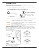
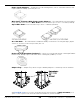
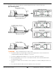
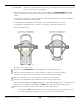


Table Of Contents
- Table of Contents
- Introduction
- Shipping Information
- Safety Considerations
- Components
- Specifications
- Installation Checklist
- Installation
- Reviewing the Safety Rules
- Gathering Your Tools
- Preparing for Electrical Work
- Reviewing the Installation Orientation
- Checking Clearances
- Selecting a Location
- Choosing a Wide or Narrow Configuration
- Installing the Safety Assemblies and Positioning the Safety Lock Cable
- Putting the Equalizing Cables into Position
- About Thread Sealants
- Identifying Hydraulic Fittings
- Routing the Hydraulic Hoses
- Creating Chalk Line Guides
- Anchoring the Posts
- Installing the Overhead Assembly and Safety Shutoff Bar
- Installing the Microswitch
- Completing the Equalizing Cables Installation
- Mounting the Power Unit
- Installing the Safety Lock Cable
- Connecting the Hydraulic Hoses
- Installing the Lift Arms
- Double Threaded Rod Installation
- Leveling
- Contact the Electrician
- Electrical Information
- Wiring the Microswitch
- Connecting the Power Unit
- Installing a Power Disconnect Switch
- Installing a Thermal Disconnect Switch
- Lubricating the Lift
- Review Final Checklist Before Operation
- Leave the Manual with the Owner/Operator
- Perform an Operational Test
- Operation
- Maintenance
- Troubleshooting
- Wiring Diagrams
- Labels
- Parts Drawings
- Automotive Lift Institute (ALI) Store
- Maintenance Log
- Maintenance Log

10AP Series Two-Post Lifts 68 P/N 5900265 — Rev. A10 — September 2023
About Safety Locks
A Safety Lock position is defined as when the Lift is engaged on both Lift’s Safety Locks at the same
height on both Posts. Having multiple Safety Lock positions allows you to lock the Lift at the best
height for what you need to do.
⚠ CAUTION Verify that both Safety Locks are engaged at the same height on both Posts. You
do not want the Lift engaged on Safety Locks of two different heights or the Safety
Lock on one Post engaged but the Safety Lock on the other Post not engaged.
Safety Lock positions are created by the Safety Lock Weldments, which are on the back of each Lift
Head. Safety Lock Weldments hit the Safety Locks and then move past them as the Lift Heads rise.
Passing:
Between Weldments:
Engaged:
Components removed for clarity. Offside Safety Lock not shown. Reference only – do not scale.
As they move past the Safety Locks, the Weldments push the Safety Lock and the Safety Lock
Release Handle down. When the Weldment is completely past the Safety Locks, the Safety Lock
Spring pulls the Lock back into place. This happens each time Safety Locks are passed, so you will
generally be hearing multiple clanks as the Lift rises and lowers.
To engage the Lift on a Safety Lock position, press the Up Button and wait until the Vehicle reaches
the desired height for the work you are going to do, then listen for the clank as the Weldments pass
the next Safety Lock position. When you hear the clank, release the Up Button, and then hold down
the Lowering Handle (on the front of the Power Unit) for a second or two to back the Weldments down
onto the just-passed Safety Locks; do not hold down the Safety Lock Release Handle.
⚠ WARNING Only leave the Lift either fully lowered or engaged on Safety Locks. If you leave
the Lift raised but not engaged on Safety Locks, the Vehicle is not
secure. It could fall, possibly damaging the Vehicle, the Lift, and injuring anyone
under the Vehicle.