
Use and Care Manual
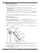
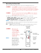

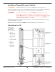


Table Of Contents
- Table of Contents
- Introduction
- Shipping Information
- Safety Considerations
- Components
- Specifications
- Installation Checklist
- Installation
- Reviewing the Safety Rules
- Gathering Your Tools
- Preparing for Electrical Work
- Reviewing the Installation Orientation
- Checking Clearances
- Selecting a Location
- Choosing a Wide or Narrow Configuration
- Installing the Safety Assemblies and Positioning the Safety Lock Cable
- Putting the Equalizing Cables into Position
- About Thread Sealants
- Identifying Hydraulic Fittings
- Routing the Hydraulic Hoses
- Creating Chalk Line Guides
- Anchoring the Posts
- Installing the Overhead Assembly and Safety Shutoff Bar
- Installing the Microswitch
- Completing the Equalizing Cables Installation
- Mounting the Power Unit
- Installing the Safety Lock Cable
- Connecting the Hydraulic Hoses
- Installing the Lift Arms
- Double Threaded Rod Installation
- Leveling
- Contact the Electrician
- Electrical Information
- Wiring the Microswitch
- Connecting the Power Unit
- Installing a Power Disconnect Switch
- Installing a Thermal Disconnect Switch
- Lubricating the Lift
- Review Final Checklist Before Operation
- Leave the Manual with the Owner/Operator
- Perform an Operational Test
- Operation
- Maintenance
- Troubleshooting
- Wiring Diagrams
- Labels
- Parts Drawings
- Automotive Lift Institute (ALI) Store
- Maintenance Log
- Maintenance Log

10AP Series Two-Post Lifts 55 P/N 5900265 — Rev. A10 — September 2023
Fill the Hydraulic Fluid reservoir with approved Hydraulic Fluid. When you receive the Power Unit,
the Reservoir is empty; you need to fill it.
The reservoir holds ≈3.5 gallons of Hydraulic Fluid, depending on which Power Unit you have.
Approved Hydraulic Fluids are any general-purpose ISO-32, ISO-46, or ISO-68 hydraulic oil or
approved automatic transmission fluids such as Dexron III, Dexron VI, Mercon V, Mercon LV, Shell
Tellus S4 / S3 / S2, or any synthetic multi-vehicle automatic transmission fluid.
⚠ WARNING Do not run the Power Unit without Hydraulic Fluid; you will damage it.
⚠ DANGER Risk of explosion: This equipment has internal arcing or parts that may spark
and should not be exposed to flammable vapors. The Power Unit’s motor should
not be located in a recessed area or below floor level. Never expose the motor to
rain or other damp environments; damage to the motor caused by water is not
covered by the warranty.
Installing a Power Disconnect Switch
⚠
WARNING A Power Disconnect Switch is not
provided with this equipment.
A Power Disconnect Switch is a National Electrical Code
(NEC) requirement. They are designed to allow the
operator to interrupt the main electrical power in the event
of an emergency or circuit fault, or when the equipment is
undergoing service or maintenance.
Make sure to install a Power Disconnect Switch that is
properly rated for the incoming power source.
Your Power Disconnect Switch must be readily accessible
and installed so that it is in easy reach of the operator or
in their line of sight. The Power Disconnect Switch must
be clearly marked to indicate its purpose.
The figure to the right details a Power Disconnect Switch
located between the Lift’s power source and its Power
Unit. A quick flip of the switch immediately cuts power to
the Lift.
In the case of the 10AP Series Lifts, the location directly
above the Power Unit is being used by the Lowering
Handle, so your Electrician may want to move the Power
Disconnect Switch location up a little.
⚠ DANGER Installing a Thermal Disconnect Switch
must be performed by a licensed,
Electrician in accordance with local and
national electrical codes.
Have the Electrician select a UL-listed Power
Disconnect Switch.