
Use and Care Manual
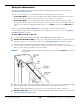
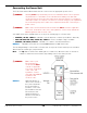

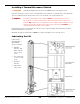
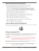


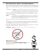
Table Of Contents
- Table of Contents
- Introduction
- Shipping Information
- Safety Considerations
- Components
- Specifications
- Installation Checklist
- Installation
- Reviewing the Safety Rules
- Gathering Your Tools
- Preparing for Electrical Work
- Reviewing the Installation Orientation
- Checking Clearances
- Selecting a Location
- Choosing a Wide or Narrow Configuration
- Installing the Safety Assemblies and Positioning the Safety Lock Cable
- Putting the Equalizing Cables into Position
- About Thread Sealants
- Identifying Hydraulic Fittings
- Routing the Hydraulic Hoses
- Creating Chalk Line Guides
- Anchoring the Posts
- Installing the Overhead Assembly and Safety Shutoff Bar
- Installing the Microswitch
- Completing the Equalizing Cables Installation
- Mounting the Power Unit
- Installing the Safety Lock Cable
- Connecting the Hydraulic Hoses
- Installing the Lift Arms
- Double Threaded Rod Installation
- Leveling
- Contact the Electrician
- Electrical Information
- Wiring the Microswitch
- Connecting the Power Unit
- Installing a Power Disconnect Switch
- Installing a Thermal Disconnect Switch
- Lubricating the Lift
- Review Final Checklist Before Operation
- Leave the Manual with the Owner/Operator
- Perform an Operational Test
- Operation
- Maintenance
- Troubleshooting
- Wiring Diagrams
- Labels
- Parts Drawings
- Automotive Lift Institute (ALI) Store
- Maintenance Log
- Maintenance Log

10AP Series Two-Post Lifts 54 P/N 5900265 — Rev. A10 — September 2023
Hydraulic System Warnings
Before applying power to the Hydraulic System note the following Warnings:
⚠
WARNING Failure to observe these warnings can result in serious personal injury including, in
rare cases, death.
⚠ WARNING The Hydraulic hoses and connections must be inspected before any attempt to
raise a Vehicle is made.
⚠ WARNING Verify all Hydraulic Hose connections and fittings, including unused auxiliary port
plugs on the Power Unit, the Flow Divider, the Cylinders and anywhere else in the
Hydraulic System are tightened.
⚠ WARNING The Power Unit is a Hydraulic Pump capable of developing pressures in excess of
5,000 psi (345 BAR). A pressure relief valve is used to set the pressure at the
desired level. Tampering with, adjusting, modifying, or removing the relief valve is
extremely dangerous and is not recommended. Only trained Hydraulics technicians
should adjust the relief valve, using calibrated hydraulic pressure gauges to assure
the proper pressure setting is achieved.
⚠ WARNING Changes to the output pressure may render the power unit incompatible with
pressure limitations of other components in the hydraulic circuit. This may cause
catastrophic failure of those components, and could result in property damage,
serious personal injury, or death.
⚠ WARNING The Hydraulic System may contain high pressure which, if suddenly released, can
cause serious injury or death.
⚠ WARNING Do not attempt to connect or disconnect Hydraulic Hoses while the equipment is
loaded or while a Vehicle is on the Lift, or the Hydraulic System is under pressure.
⚠ WARNING Keep bare hands away from Hydraulic Fluid; always wear gloves when handling
Hydraulic Fluid, Cylinders or Hydraulic Hoses.
⚠ WARNING When handling Hydraulic Fluid, always observe the safety instructions from the
manufacturer.
⚠ WARNING Always promptly clean any Hydraulic Fluid spills. If a leak is the source of the spill,
lockout the Lift to prevent use until the Hydraulic System is repaired.
To prepare the Power Unit:
Have the Electrician locate the Pigtail coming out of the Electrical Box on the Power Unit.
Open the Electrical Box, remove the Pigtail, and then either:
– Wire the Power Unit directly into the facility’s electrical system and protected by an appropriate
circuit breaker.
– Wire a power cord (with appropriate plug) inside the Electrical Box to the wiring that was
connected to the Pigtail.
Wire the Microswitch(es) into the incoming power. Refer to Wiring Diagrams for wiring
information.