
Use and Care Manual
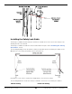
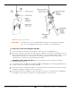
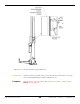
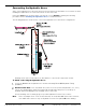
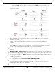
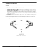
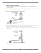
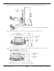
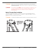
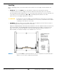
Table Of Contents
- Table of Contents
- Introduction
- Shipping Information
- Safety Considerations
- Components
- Specifications
- Installation Checklist
- Installation
- Reviewing the Safety Rules
- Gathering Your Tools
- Preparing for Electrical Work
- Reviewing the Installation Orientation
- Checking Clearances
- Selecting a Location
- Choosing a Wide or Narrow Configuration
- Installing the Safety Assemblies and Positioning the Safety Lock Cable
- Putting the Equalizing Cables into Position
- About Thread Sealants
- Identifying Hydraulic Fittings
- Routing the Hydraulic Hoses
- Creating Chalk Line Guides
- Anchoring the Posts
- Installing the Overhead Assembly and Safety Shutoff Bar
- Installing the Microswitch
- Completing the Equalizing Cables Installation
- Mounting the Power Unit
- Installing the Safety Lock Cable
- Connecting the Hydraulic Hoses
- Installing the Lift Arms
- Double Threaded Rod Installation
- Leveling
- Contact the Electrician
- Electrical Information
- Wiring the Microswitch
- Connecting the Power Unit
- Installing a Power Disconnect Switch
- Installing a Thermal Disconnect Switch
- Lubricating the Lift
- Review Final Checklist Before Operation
- Leave the Manual with the Owner/Operator
- Perform an Operational Test
- Operation
- Maintenance
- Troubleshooting
- Wiring Diagrams
- Labels
- Parts Drawings
- Automotive Lift Institute (ALI) Store
- Maintenance Log
- Maintenance Log

10AP Series Two-Post Lifts 48 P/N 5900265 — Rev. A10 — September 2023
Slide the Arm Lock Pin through the holes in the Lift Head and the Lift Arm Assembly.
Push a Snap Ring into its grooves on the bottom of the Arm Lock Guide Rod.
Secure a Set Screw on either side of the Lift Head Pin; two Set Screws per each Lift Head Pin.
Repeat Steps 1 – 6 for the other three Lift Arm Assemblies.
Reference only – do not scale. Shown with optional equipment