
Use and Care Manual
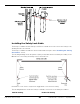
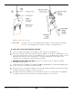
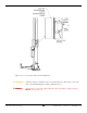
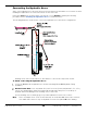
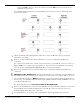
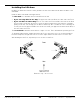
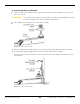
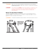
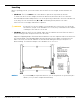
Table Of Contents
- Table of Contents
- Introduction
- Shipping Information
- Safety Considerations
- Components
- Specifications
- Installation Checklist
- Installation
- Reviewing the Safety Rules
- Gathering Your Tools
- Preparing for Electrical Work
- Reviewing the Installation Orientation
- Checking Clearances
- Selecting a Location
- Choosing a Wide or Narrow Configuration
- Installing the Safety Assemblies and Positioning the Safety Lock Cable
- Putting the Equalizing Cables into Position
- About Thread Sealants
- Identifying Hydraulic Fittings
- Routing the Hydraulic Hoses
- Creating Chalk Line Guides
- Anchoring the Posts
- Installing the Overhead Assembly and Safety Shutoff Bar
- Installing the Microswitch
- Completing the Equalizing Cables Installation
- Mounting the Power Unit
- Installing the Safety Lock Cable
- Connecting the Hydraulic Hoses
- Installing the Lift Arms
- Double Threaded Rod Installation
- Leveling
- Contact the Electrician
- Electrical Information
- Wiring the Microswitch
- Connecting the Power Unit
- Installing a Power Disconnect Switch
- Installing a Thermal Disconnect Switch
- Lubricating the Lift
- Review Final Checklist Before Operation
- Leave the Manual with the Owner/Operator
- Perform an Operational Test
- Operation
- Maintenance
- Troubleshooting
- Wiring Diagrams
- Labels
- Parts Drawings
- Automotive Lift Institute (ALI) Store
- Maintenance Log
- Maintenance Log

10AP Series Two-Post Lifts 42 P/N 5900265 — Rev. A10 — September 2023
Reference only – do not scale.
⚠
WARNING You will need to access the Overhead Assembly to route the Safety Lock Cable.
Use care to avoid falling when working on a ladder or other lifting device.
To route and connect the Safety Lock Cable:
Locate the Safety Lock Cable. This should be coiled at the top of the Offside Post.
Route the non-button end under the Safety Sheave, upwards on the inside of the Offside Post, up
and over the Safety Sheave at the top of the Offside Post, across the Overhead Assembly, over the
Safety Sheave at the top of the Powerside Post, and then downwards, on the inside of the
Powerside Post, towards the Powerside Safety Assembly.
Switching to the Powerside Post, route the non-button end of the Safety Lock Cable
through the Safety Sheave.
Temporarily remove the M6 Hex Head Bolt (5530031) and M6 Split Lock Washer (5545026) that is
loosely secured to the Safety Lock Release Handle.
Route the Safety Lock Cable through the hole in the Safety Release Handle, then replace the Bolt
and Split-Lock Washer. Tightly secure the connection.
Install the Safety Cover (5716072) to the Powerside Post; there is no Safety Cover for the Offside
Post. Make sure the Safety Lock Release is usable through the slot on the front.