
Use and Care Manual
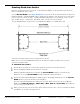
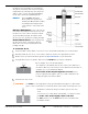
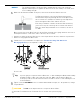
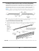
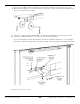
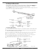
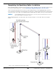
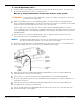
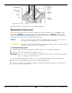
Table Of Contents
- Table of Contents
- Introduction
- Shipping Information
- Safety Considerations
- Components
- Specifications
- Installation Checklist
- Installation
- Reviewing the Safety Rules
- Gathering Your Tools
- Preparing for Electrical Work
- Reviewing the Installation Orientation
- Checking Clearances
- Selecting a Location
- Choosing a Wide or Narrow Configuration
- Installing the Safety Assemblies and Positioning the Safety Lock Cable
- Putting the Equalizing Cables into Position
- About Thread Sealants
- Identifying Hydraulic Fittings
- Routing the Hydraulic Hoses
- Creating Chalk Line Guides
- Anchoring the Posts
- Installing the Overhead Assembly and Safety Shutoff Bar
- Installing the Microswitch
- Completing the Equalizing Cables Installation
- Mounting the Power Unit
- Installing the Safety Lock Cable
- Connecting the Hydraulic Hoses
- Installing the Lift Arms
- Double Threaded Rod Installation
- Leveling
- Contact the Electrician
- Electrical Information
- Wiring the Microswitch
- Connecting the Power Unit
- Installing a Power Disconnect Switch
- Installing a Thermal Disconnect Switch
- Lubricating the Lift
- Review Final Checklist Before Operation
- Leave the Manual with the Owner/Operator
- Perform an Operational Test
- Operation
- Maintenance
- Troubleshooting
- Wiring Diagrams
- Labels
- Parts Drawings
- Automotive Lift Institute (ALI) Store
- Maintenance Log
- Maintenance Log

10AP Series Two-Post Lifts 39 P/N 5900265 — Rev. A10 — September 2023
To route the Equalizing Cables:
Using a Forklift or Shop Crane, manually raise both Lift Heads about 28 inches / 711 mm off the
ground and engage them on the closest Safety Lock.
Measure to verify both Lift Heads are the same distance off the ground.
⚠ WARNING You must use a proper lifting device such as a Forklift or Shop Crane to raise and
position the Lift components.
Make sure the Button Ends of both Equalizing Cables are still in the Slots in their Cable Button
Stops, that both Equalizing Cables go under the Post Sheave in their Posts, and that the Threaded
Ends have been routed through the Hole at the Top of the Lift Head.
If either cable is not correct, fix it; you cannot continue until the Equalizing Cables are in their
correct starting positions. Remember, for a Wide Configuration, use the Button End at the very end
of the Equalizing Cable. For a Narrow Configuration, use the Button End away from the end of the
Equalizing Cable.
Choose which one of the two Equalizing Cables you are going to put into position first, then
remove the Nut from the Threaded End of that Cable.
NOTICE The Overhead Assembly Sheave, Sheave Pin, and Hair Pin were previously removed. If
they were mistakenly re-installed, you need to remove them again.
Route the Threaded End of the Equalizing Cable up on the inside of the Post, over the Overhead
Sheave Assembly, and then out over the top of the Overhead Assembly.
Lubricate the Sheave Pin and Bearing with Red Lithium Grease, then re-install the Overhead
Assembly Sheave, Sheave Pin, and Hair Pin.
At the other Post, remove the Nut from the Threaded End of the other Equalizing Cable.
Route the Threaded End over the top of the Overhead Assembly Sheave, and then down the Post
towards the Lift Head.
Lubricate the Sheave Pin and Bearing with Red Lithium Grease, then re-install the Overhead
Assembly Sheave, Sheave Pin, and Hair Pin.
Put the Threaded End of the Equalizing Cable through the hole at the top of the Lift Head, then
install the Nut and securely tighten.