
Use and Care Manual
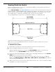
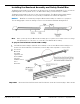
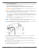
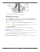
Table Of Contents
- Table of Contents
- Introduction
- Shipping Information
- Safety Considerations
- Components
- Specifications
- Installation Checklist
- Installation
- Reviewing the Safety Rules
- Gathering Your Tools
- Preparing for Electrical Work
- Reviewing the Installation Orientation
- Checking Clearances
- Selecting a Location
- Choosing a Wide or Narrow Configuration
- Installing the Safety Assemblies and Positioning the Safety Lock Cable
- Putting the Equalizing Cables into Position
- About Thread Sealants
- Identifying Hydraulic Fittings
- Routing the Hydraulic Hoses
- Creating Chalk Line Guides
- Anchoring the Posts
- Installing the Overhead Assembly and Safety Shutoff Bar
- Installing the Microswitch
- Completing the Equalizing Cables Installation
- Mounting the Power Unit
- Installing the Safety Lock Cable
- Connecting the Hydraulic Hoses
- Installing the Lift Arms
- Double Threaded Rod Installation
- Leveling
- Contact the Electrician
- Electrical Information
- Wiring the Microswitch
- Connecting the Power Unit
- Installing a Power Disconnect Switch
- Installing a Thermal Disconnect Switch
- Lubricating the Lift
- Review Final Checklist Before Operation
- Leave the Manual with the Owner/Operator
- Perform an Operational Test
- Operation
- Maintenance
- Troubleshooting
- Wiring Diagrams
- Labels
- Parts Drawings
- Automotive Lift Institute (ALI) Store
- Maintenance Log
- Maintenance Log

10AP Series Two-Post Lifts 31 P/N 5900265 — Rev. A10 — September 2023
Creating Chalk Line Guides
Based on the Specifications for your Lift, create Chalk Line Guides on the ground for the two Posts
prior to moving them into position.
Use the Overall Width value in Specifications for your Lift model to determine where to place the
Chalk Line Guides. The Overall Width value is defined as the distance from the back of one base plate
to the back of the other base plate. The Overall Width setting may be set to Narrow (135 in. / 3,431
mm) or Wide (145 in. / 3,683 mm), depending on the selection for your Lift model.
The following illustration shows how to create Chalk Line Guides for a 10AP Series Lift.
Top View of the Base Plates. Not all components are shown.
Make sure to choose the Width Overall value for the Narrow or Wide orientation, based on the
selection you made earlier.
To add Chalk Line Guides:
Decide where you want to locate the Lift. Verify the clearances around the Lift area.
Create an Alignment Chalk Line at the Front of the Lift.
Make the Alignment Chalk Line longer than the Overall Width setting for your Lift model.
Make sure to use the Overall Width setting for Narrow or Wide orientation.
Create two Perpendicular Chalk Lines at 90° angles to the Alignment Chalk Lines at the Overall
Width distance for the Lift model you are installing.
The two Perpendicular Chalk Lines must be a specified distance from each other, the Overall
Width setting Narrow (135 in. / 3,431 mm) or Wide (145 in. / 3,683 mm), depending on
the selection for your Lift model.
When you move the Posts into position, put the Base Plates into the corners created by the Chalk
Line Guides, as shown in the figure above.