
Use and Care Manual
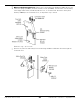
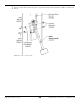
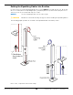
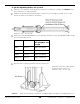
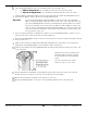
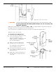
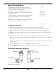
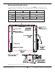
Table Of Contents
- Table of Contents
- Introduction
- Shipping Information
- Safety Considerations
- Components
- Specifications
- Installation Checklist
- Installation
- Reviewing the Safety Rules
- Gathering Your Tools
- Preparing for Electrical Work
- Reviewing the Installation Orientation
- Checking Clearances
- Selecting a Location
- Choosing a Wide or Narrow Configuration
- Installing the Safety Assemblies and Positioning the Safety Lock Cable
- Putting the Equalizing Cables into Position
- About Thread Sealants
- Identifying Hydraulic Fittings
- Routing the Hydraulic Hoses
- Creating Chalk Line Guides
- Anchoring the Posts
- Installing the Overhead Assembly and Safety Shutoff Bar
- Installing the Microswitch
- Completing the Equalizing Cables Installation
- Mounting the Power Unit
- Installing the Safety Lock Cable
- Connecting the Hydraulic Hoses
- Installing the Lift Arms
- Double Threaded Rod Installation
- Leveling
- Contact the Electrician
- Electrical Information
- Wiring the Microswitch
- Connecting the Power Unit
- Installing a Power Disconnect Switch
- Installing a Thermal Disconnect Switch
- Lubricating the Lift
- Review Final Checklist Before Operation
- Leave the Manual with the Owner/Operator
- Perform an Operational Test
- Operation
- Maintenance
- Troubleshooting
- Wiring Diagrams
- Labels
- Parts Drawings
- Automotive Lift Institute (ALI) Store
- Maintenance Log
- Maintenance Log

10AP Series Two-Post Lifts 30 P/N 5900265 — Rev. A10 — September 2023
To put the Hydraulic Hoses into position:
Locate the 4 Hydraulic Hoses and necessary Hydraulic Fittings: Two Elbow Fittings (5550113), one
Tee Fitting (5550003), and one Nipple Fitting (5550095 – for wide configurations only).
NOTICE The Power Unit Elbow Fitting (5550183) and the Short Hydraulic Hose cannot be
installed at this point, as the Power Unit is not yet in place.
Starting most of the way up the Powerside Post, push the single fitting (-06 JIC) on the
Bulkhead Tee Hydraulic Fitting (5550003) through the hole above the Power Unit Mounting Bracket
from inside the Powerside Post.
NOTICE There is only one Tee Fitting, and it is installed on the Powerside Post above where the
Power Unit will be installed.
Tighten the Nut on the outside of the Powerside Post to hold the Bulkhead Tee Fitting in place.
Switching to the bottom of the Powerside Post, remove the Shipping Plug from the
Hydraulic Hose Connector on the bottom of the Hydraulic Cylinder.
Important Keep a rag nearby in case some fluid leaks out of the Hydraulic Hose Connector
when you remove the Shipping Plug.
Connect one of the two Elbow Fittings (5550113) to the Hydraulic Hose Connector; tighten the
Elbow Fitting appropriately.
Point the JIC end of the Fitting towards the side of the Post with the Clips. Use liquid thread
sealant on the NPT male threads only.
Turn the Hydraulic Cylinder so that the Elbow Hydraulic Fitting is accessible from the bottom back
side of the Powerside Post.
NOTICE When routing Hydraulic Hoses, after they are positioned correctly, put them into the
nearby Clips and lightly crimp the Clips together along the side of each Post. When all
Hydraulic Hoses have been installed, go back and fully crimp all the Clips.
Take the Medium Hydraulic Hose, connect the Straight End to the bottom of the Tee Fitting
(5550003), and tighten securely.
Push the Curved End of the Medium Hydraulic Hose down to the bottom of the Powerside Post
and connect it to the JIC end of the Elbow Hydraulic Fitting (5550113); tighten securely.
Switching to the Offside Post, connect the other Elbow Fitting (5550113) to the Hydraulic
Hose Port at the bottom of the Hydraulic Cylinder.
Tighten the Elbow Fitting securely; make sure to leave the unconnected end of the fitting pointing
towards the side with the Clips.
Take the Long Hydraulic Hose, push the Curved End down through the Post, then connect the
Curved End to the Elbow Fitting (5550113) you just connected and tighten securely.
Make sure to clip the Long Hydraulic Hose to the Clips in the Post.
Carefully coil up and bind the rest of the Long Hydraulic Hose, then leave it resting on top of the
Offside Post until later in the installation.
You should now have the Long Hydraulic Hose connected to the bottom of the Hydraulic Cylinder
in the Offside Post, with the rest of the Long Hydraulic Hose coiled up at the top of the Offside
Post. It will be connected to the rest of the Hydraulic System later in the installation.