
Use and Care Manual
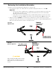
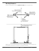
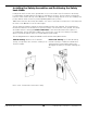
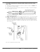
Table Of Contents
- Table of Contents
- Introduction
- Shipping Information
- Safety Considerations
- Components
- Specifications
- Installation Checklist
- Installation
- Reviewing the Safety Rules
- Gathering Your Tools
- Preparing for Electrical Work
- Reviewing the Installation Orientation
- Checking Clearances
- Selecting a Location
- Choosing a Wide or Narrow Configuration
- Installing the Safety Assemblies and Positioning the Safety Lock Cable
- Putting the Equalizing Cables into Position
- About Thread Sealants
- Identifying Hydraulic Fittings
- Routing the Hydraulic Hoses
- Creating Chalk Line Guides
- Anchoring the Posts
- Installing the Overhead Assembly and Safety Shutoff Bar
- Installing the Microswitch
- Completing the Equalizing Cables Installation
- Mounting the Power Unit
- Installing the Safety Lock Cable
- Connecting the Hydraulic Hoses
- Installing the Lift Arms
- Double Threaded Rod Installation
- Leveling
- Contact the Electrician
- Electrical Information
- Wiring the Microswitch
- Connecting the Power Unit
- Installing a Power Disconnect Switch
- Installing a Thermal Disconnect Switch
- Lubricating the Lift
- Review Final Checklist Before Operation
- Leave the Manual with the Owner/Operator
- Perform an Operational Test
- Operation
- Maintenance
- Troubleshooting
- Wiring Diagrams
- Labels
- Parts Drawings
- Automotive Lift Institute (ALI) Store
- Maintenance Log
- Maintenance Log

10AP Series Two-Post Lifts 19 P/N 5900265 — Rev. A10 — September 2023
To assemble and install the two Safety Assemblies and pre-position the safety
release cable:
Put both Posts either flat on the ground or elevated on a sawhorse or similar. The insides of the
Posts must be accessible, facing up.
Slide the Lift Heads away from the bottom of both Posts. Far enough to clear the Latch Support
Plate and provide room to work.
Illustration above is a top view looking at the inside of the Lift Post. Not to Scale. Some
components removed for clarity.
Begin on the Offside Post, retrieve the Offside Safety Block (5737177), two extension springs
(5540047), four M6 x 20 machine screws (5530065) and the Pivot Pin (5746494) from the Parts
Bag. Overlap the Safety Block over the Latch Support Plate welded to the Offside Lift Post. Then
attach the extension Springs. Overlapping these parts will ease the Extension Spring installation.
Then move the Safety Block to overlap the Latch Support Plate and secure using the Safety Pivot
Pin as shown below.
Not to scale. Components removed for clarity.