
Use and Care Manual
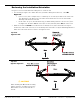
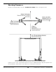
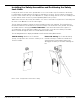
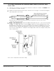
Table Of Contents
- Table of Contents
- Introduction
- Shipping Information
- Safety Considerations
- Components
- Specifications
- Installation Checklist
- Installation
- Reviewing the Safety Rules
- Gathering Your Tools
- Preparing for Electrical Work
- Reviewing the Installation Orientation
- Checking Clearances
- Selecting a Location
- Choosing a Wide or Narrow Configuration
- Installing the Safety Assemblies and Positioning the Safety Lock Cable
- Putting the Equalizing Cables into Position
- About Thread Sealants
- Identifying Hydraulic Fittings
- Routing the Hydraulic Hoses
- Creating Chalk Line Guides
- Anchoring the Posts
- Installing the Overhead Assembly and Safety Shutoff Bar
- Installing the Microswitch
- Completing the Equalizing Cables Installation
- Mounting the Power Unit
- Installing the Safety Lock Cable
- Connecting the Hydraulic Hoses
- Installing the Lift Arms
- Double Threaded Rod Installation
- Leveling
- Contact the Electrician
- Electrical Information
- Wiring the Microswitch
- Connecting the Power Unit
- Installing a Power Disconnect Switch
- Installing a Thermal Disconnect Switch
- Lubricating the Lift
- Review Final Checklist Before Operation
- Leave the Manual with the Owner/Operator
- Perform an Operational Test
- Operation
- Maintenance
- Troubleshooting
- Wiring Diagrams
- Labels
- Parts Drawings
- Automotive Lift Institute (ALI) Store
- Maintenance Log
- Maintenance Log

10AP Series Two-Post Lifts 18 P/N 5900265 — Rev. A10 — September 2023
Installing the Safety Assemblies and Positioning the Safety
Lock Cable
Leaving both Lift Posts flat on the ground with access to the inside of the Post will ease the Safety
Lock installation and threading of the Safety Lock Cable into position. This procedure is intended to
leave the cable coiled at the top of the Offside Post, ready for routing after the Posts are standing. This
position will also make it easier to put the Equalizing Cables into position.
10AP Series Lifts have two Safety Assemblies: one on the Powerside Post (above the Power Unit) and
the other on the Offside Post at the same height.
The two Safety Assemblies engage the Lift head and prevent it from lowering. The Safety Release
mechanism allows the Lift Head to move past the Safety Locks and lower to the ground. The Safety
Assemblies must be disengaged at the same time so that both Lift Heads lower together. To
accomplish this, the two Safety Assemblies are connected to each other via a Safety Lock Cable,
which is routed through the Lift Posts and the Overhead Assembly.
The following illustrations display the Offside and Powerside Safety Mechanisms.
Offside Safety: Similar to the Powerside
Safety, except that it does not have a Safety Lock
Release Handle.
Powerside Safety: The Powerside Safety
includes a Safety Lock Release Handle and
spring, which is pushed down and used to
disengage the Safety Locks when lowering the
Lift.
Not to scale. Components removed for clarity.