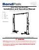
645 Lemonwood Dr. Santa Paula, CA 93060 USA Toll Free: (800) 253-2363 Telephone: (805) 933-9970 bendpak.com Clear Floor Two-Post Lifts Installation and Operation Manual Manual P/N 5900265 — Manual Revision A10 — September 2023 Models: • 10AP • 10AP-168 • 10APX • 10APX-181 Original instructions in the English language 10AP model shown above. ⚠ DANGER Designed and engineered by BendPak Inc. in Southern California, USA. Made in China.
Manual. 10AP Series Two-Post Lifts, Installation and Operation Manual, Manual Part Number 5900265, Manual Revision A10, released September 2023. Copyright. Copyright ©2023 by BendPak Inc. All rights reserved. You may make copies of this document if you agree that: full attribution goes to BendPak Inc., you are not authorized to make changes to the content, you do not gain any rights to this content, and you will not use the copies for commercial purposes. Trademarks.
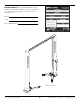
Unit Information. Enter the Model Number, Serial Number, and the Date of Manufacture from the ID label on your unit. This information is required for part or warranty issues. Model: Serial: Date of Manufacture: 10AP model shown. 10AP Series Two-Post Lifts 3 P/N 5900265 — Rev.
Table of Contents Introduction 4 Maintenance 69 Shipping Information 5 Troubleshooting 71 Safety Considerations 5 Wiring Diagrams 75 Components 8 Labels 77 Specifications 9 Parts Drawings 80 Installation Checklist 11 ALI Store 97 Installation 12 Maintenance Log 98 Operation 59 Introduction This manual describes the four BendPak Two-Post Lift models: • • • • 10AP. A Two-Post Lift with overall height of 145 in. / 3,683 mm that raises Vehicles up to 10,000 pounds (4,536 kg).
Shipping Information Your equipment was carefully checked before shipping. Nevertheless, you should thoroughly inspect the shipment before you sign to acknowledge that you received it. When you sign the bill of lading, it tells the carrier that the items on the invoice were received in good condition. Do not sign the bill of lading until after you have inspected the shipment.
• • • • • • • • • Do not operate equipment with a damaged cord or if the equipment has been dropped or damaged – until it has been examined by a qualified service person. Do not let a cord hang over the edge of a table, bench, or counter or come in contact with hot manifolds or moving fan blades. Loop the power cord around equipment when storing. If an extension cord is necessary, a cord with a current rating equal to or greater than that of the equipment should be used.
Symbols Following are symbols used in this manual: ⚠ DANGER ⚠ WARNING Calls attention to a hazard that will result in death or injury. Calls attention to a hazard or unsafe practice that could result in death or injury. ⚠ CAUTION Calls attention to a hazard or unsafe practice that could result in personal injury, product damage, or property damage. NOTICE Calls attention to a situation that could result in product or property damage.
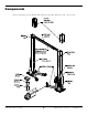
Components Not all components shown. Models with extensions are taller. Reference only – do not scale. 10AP Series Two-Post Lifts 8 P/N 5900265 — Rev.
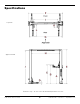
Specifications Top View Approach View Reference only – do not scale. Shown with Optional Accessories. 10AP Series Two-Post Lifts 9 P/N 5900265 — Rev.
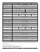
Model 10AP 10AP-168 10APX Lifting Capacity 10,000 lbs. / 4,536 kg Max. Capacity — Front Axle 5,000 lbs. / 2,268 kg Max. Capacity — Rear Axle 5,000 lbs. / 2,268 kg 10APX-181 A – Max. Rise 69 in. / 1,753 mm 75.5 in. / 1,918 mm B – Lifting Height w/ Pad1 73 in. / 1,854 mm 79.5 in. / 2,007 mm 82.5 in. / 2,095 mm 89 in. / 2,261 mm C – Max. Lifting Height1 D – Min. Height w/ Pad E – Overall Height 4 in. / 102 mm 145 in. / 3,683 mm 168 in. / 4,267 mm 157 in.
Installation Checklist Following are the steps needed to install a 10AP Series Two-Post Lift; perform them in this order. ☐ 1. Review the Safety Rules. ☐ 2. Make sure you have the necessary tools. ☐ 3. Plan for Electrical Work. ☐ 4. Review the Installation Orientation. ☐ 5. Review Clearances around the Lift. ☐ 6. Select the Installation Location. ☐ 7. Choose a Wide or Narrow Configuration (do not proceed until you have chosen). ☐ 8. Install the Safety Assemblies and position the Safety Cable. ☐ 9.
Installation The installation process includes multiple steps. Perform them in the order listed. ⚠ WARNING Use only the factory-supplied parts shipped with your Lift.
Preparing for Electrical Work You will need to have a licensed, certified Electrician available at some point during the installation. ⚠ DANGER NOTICE All wiring must be performed by a licensed, certified Electrician in accordance with applicable local, state, and federal electrical codes, rules, and regulations, such as state and federal OSHA regulations and electrical codes.
Reviewing the Installation Orientation Keep these factors in mind when deciding how to orient the Lift: • • The first thing to figure out is which direction you will be driving the Vehicles in, called the Approach. o In most cases, this is simple: there’s a driveway on one side and a wall on the other side. The driveway is your Approach. This makes the wall side the Front of the Lift and the driveway side the Rear of the Lift.
Checking Clearances Clearance around and above the Lift is required for safety. Refer to the figures below. Figures are not to scale, shown with optional accessories. Additional distance may be required on the Front and Rear to allow Vehicles to be driven in or out from these directions. 10AP Series Two-Post Lifts 15 P/N 5900265 — Rev.
Selecting a Location When selecting the location for your Lift, consider the following: • • • • • Architectural plans. Consult the architectural plans for the desired location. Make sure there are no contradictions between what you want to do and what the plans show. Available space. Make sure there is enough space for the Lift: front, back, sides, and above. Refer to Specifications for exact measurements.
Choosing a Wide or Narrow Configuration 10AP Series Two-Post Lifts can be installed in a Wide or Narrow Configuration: • Wide Configuration. The Posts are farther apart, which means you can raise wider Vehicles on the Lift. This is usually the best choice if your Lift location is wide enough to support it. When installing the Equalizing Cables, use the Button End at the very end of the cable. The following drawing shows an Equalizing Cable; the ends are exaggerated for clarity. • Narrow Configuration.
Installing the Safety Assemblies and Positioning the Safety Lock Cable Leaving both Lift Posts flat on the ground with access to the inside of the Post will ease the Safety Lock installation and threading of the Safety Lock Cable into position. This procedure is intended to leave the cable coiled at the top of the Offside Post, ready for routing after the Posts are standing. This position will also make it easier to put the Equalizing Cables into position.
To assemble and install the two Safety Assemblies and pre-position the safety release cable: Put both Posts either flat on the ground or elevated on a sawhorse or similar. The insides of the Posts must be accessible, facing up. Slide the Lift Heads away from the bottom of both Posts. Far enough to clear the Latch Support Plate and provide room to work. Illustration above is a top view looking at the inside of the Lift Post. Not to Scale. Some components removed for clarity.
Reference only – do not scale. Locate the Safety Lock Cable. This is a long, thin Wire Rope Cable with a Button swaged onto one end and nothing on the other end. Thread the cable through the Offside Safety Block as shown above. Part Number and Cable length varies based on Lift Model. Model Part Number Safety Cable Dia. and Length 10AP 5595793 Ø1.8 x 7,773 mm 10AP-168 5595831 Ø1.8 x 8,865 mm 10APX 5595832 Ø1.8 x 8,103 mm 10AP-181 5595833 Ø1.
Move to the Powerside Post, Retrieve the Powerside Safety Weldment (5601516), the two extension springs (5540047) and four machine screws (5530045), then attach it over the Safety Latch Support Block that is welded inside the Post, as shown below. Attach the Safety Pivot Holder (5700404) to the Powerside Post, as depicted in step 7 below. Reference only – do not scale. Connect the Pivot Pin and Safety Pivot Holder using the M8 x 25 Machine Screw through the Powerside Post.
After the Safety Pivot Holder is in place, attach the Safety Release Handle (5761017) as depicted below. Reference only – do not scale. 10AP Series Two-Post Lifts 22 P/N 5900265 — Rev.
Putting the Equalizing Cables into Position It is much easier to put the Equalizing Cables into position before you stand up the Posts. Note that this is not a full install of the Equalizing Cables, just putting them into position and looping the excess at the top of the Post secured with a Zip Tie or Tape. NOTICE ⚠ CAUTION The two Equalizing Cables are the same length. BendPak recommends wearing safety gloves when handling the Equalizing Cables.
To put the Equalizing Cables into position: Put both Posts either flat on the ground or elevated on a sawhorse or similar. The insides of the Posts must be accessible, facing up. Slide the Lift Heads away from the bottom of both Posts. Far enough to provide access to the bottom of the Lift Post and the Post Sheave. Reference only – do not scale. Retrieve the two Equalizing Cables for your Lift. Each model has a specific Equalizing Cable length as noted in the table below.
Take an Equalizing Cable and locate the Button End you are going to use: • • For Wide Configurations, use the Button end at the very end of the cable. For Narrow Configurations, use the Button end away from the end of the cable. Push the Button end up through the bottom of the Lift Head up towards the Cable Button Stop, then push the Button end into the Slot in the Cable Button Stop.
Reference only – do not scale. ⚠ WARNING Verify the Cylinder Clamps are positioned at the top of the Lift Head and secured. Do not operate the Lift if the Cylinder Clamps are not secured on the Hydraulic Cylinders. 10AP Series model numbers ending with -168 or -181 are supplied with Post Extensions that raise the height of the Posts and allow you to raise taller Vehicles. The Post Extensions are slipped over the top of both Posts and then bolted into place. Reference only – do not scale.
IMPORTANT! PLEASE READ NOW Hydraulic Fluid Contamination poses a serious issue for your Lift; contaminants such as water, dirt, or other debris can get into the Hydraulic Hoses and Fittings on the Lift, making your new Lift inoperable and unusable. Your Lift is shipped with clean components; however, BendPak strongly recommends that you take secondary precautions and clean all Hydraulic Hoses and Fittings prior to making connections.
About Thread Sealants Liquid Thread Sealant lubricates and fills the gaps between the Fitting threads and leaves no residue that could contaminate the Hydraulic Fluid. Other types of Thread Sealants (like Teflon Tape) can shred during installation or removal and eventually enter the Hydraulic System. Thread Sealant can be used with most Hydraulic Fittings, although you probably only need to use with NPT connectors. Apply the thread sealant when the ambient temperature is between +46.
Routing the Hydraulic Hoses It is easier to put some hydraulic components into position before you stand up the Posts. All 10AP Series Lifts use either three or four Hydraulic Hoses (shown in the illustration below): Lift Model 10AP 10AP-168 10 APX 10APX-181 Hose A 5570277 5570278 Hose B 5570279 5570023 Hose C Hose D 5570291 5570292 5570293 5570095 5570174 (Wide configuration ONLY) All Hydraulic Hoses and Hydraulic Fitting locations are detailed in the drawing below.
To put the Hydraulic Hoses into position: Locate the 4 Hydraulic Hoses and necessary Hydraulic Fittings: Two Elbow Fittings (5550113), one Tee Fitting (5550003), and one Nipple Fitting (5550095 – for wide configurations only). NOTICE The Power Unit Elbow Fitting (5550183) and the Short Hydraulic Hose cannot be installed at this point, as the Power Unit is not yet in place.
Creating Chalk Line Guides Based on the Specifications for your Lift, create Chalk Line Guides on the ground for the two Posts prior to moving them into position. Use the Overall Width value in Specifications for your Lift model to determine where to place the Chalk Line Guides. The Overall Width value is defined as the distance from the back of one base plate to the back of the other base plate. The Overall Width setting may be set to Narrow (135 in. / 3,431 mm) or Wide (145 in.
Anchoring the Posts ⚠ DANGER Pay special attention when installing the Posts. If done incorrectly, the Lift could fall over, potentially causing damage to the Vehicle, the Lift, and injuring bystanders. BendPak strongly recommends consulting a Concrete Specialist early in your planning process for Lift installations.
Lift buyers are responsible for conforming to all regional, structural, and seismic anchoring requirements specified by any other agencies and/or codes, such as the Uniform Building Code and/or International Building Code. NOTICE Consider not torquing the Anchor Bolts into position yet. Installing the Overhead Assembly and doing final leveling may be easier if there is some play in the Posts. Effective Embedment is the location in the Hole where the Expansion Sleeve presses into the Concrete.
The holding strength of an Anchor Bolt is partially based on the how cleanly the Expansion Sleeve presses against the Concrete. If the hole is dirty or too wide, there is less holding strength. NOTICE Make sure the Washer and Nut are in place, then insert the Anchor Bolt into the hole. The Expansion Sleeve of the Anchor Bolt may prevent the Anchor Bolt from passing through the hole in the Base Plate; this is normal.
Installing the Overhead Assembly and Safety Shutoff Bar The Overhead Assembly is installed above and between the Powerside and Offside Posts. It holds the Equalizing Cables, the Hydraulic Hoses, the Microswitch wiring, and the Safety Lock Cable. The Overhead Assembly is two pieces that are bolted together. The Overhead Assembly and the Safety Shutoff Bar come from the factory already assembled in the Narrow Configuration. NOTICE BendPak recommends placing the Overhead Assembly on sawhorses to prepare it.
Remove all four Overhead Assembly Sheaves, their Pins and Cotter Pins from the ends of the Overhead Assembly pieces. Keep the Sheave components nearby, you will be reinstalling them in the same order in the next section. Attach one end of the Safety Shutoff Bar to the Overhead Assembly, as shown below; use the same type of M10 hardware to secure the other end of the Shutoff Bar.
Installing the Microswitch The following procedure describes how to install a Microswitch on the Overhead Assembly but does not describe how to wire it; wiring is covered later in the installation. The Microswitch wiring goes over the Overhead Assembly and down the Powerside Post to the Power Unit. If you have two Microswitches because you are using a three-phase Power Unit, simply install the two of them next to each other in the Microswitch Bracket.
Completing the Equalizing Cables Installation Both Equalizing Cables should have been put into position coiled at the top of the Lift Posts before the Posts were raised, which was covered in Putting the Equalizing Cables into Position. This section picks up where that section left off: the Button Ends of the Equalizing Cables (on both Posts) have been installed, routed around the Post Sheaves, and then pushed up above the Lift Head.
To route the Equalizing Cables: Using a Forklift or Shop Crane, manually raise both Lift Heads about 28 inches / 711 mm off the ground and engage them on the closest Safety Lock. Measure to verify both Lift Heads are the same distance off the ground. ⚠ WARNING You must use a proper lifting device such as a Forklift or Shop Crane to raise and position the Lift components.
Reference only – do not scale. Perform Steps 3 through 9 for the other Equalizing Cable. Mounting the Power Unit This section describes how to mount the Power Unit to the Powerside Post. You do not need an Electrician to mount the Power Unit, but you do need an Electrician to connect the Power Unit. Refer to Connecting the Power Unit for installation information for your Electrician and specific information about the Power Unit that came with your Lift.
Installing the Safety Lock Cable The Safety Lock Cable and the Safety Lock Release Handle are used to release the Safety Locks, allowing the Lift to be lowered. The Safety Lock Cable should have been installed and left in place in the Installing the Safety Assemblies section, The following drawing shows the path the Safety Lock Cable travels from Safety Assembly on the Offside Post to the Safety Assembly on the Powerside Post. Not drawn to scale. Some components exaggerated or not shown for clarity.
Reference only – do not scale. ⚠ WARNING You will need to access the Overhead Assembly to route the Safety Lock Cable. Use care to avoid falling when working on a ladder or other lifting device. To route and connect the Safety Lock Cable: Locate the Safety Lock Cable. This should be coiled at the top of the Offside Post.
Figure not to scale. Shown with optional equipment. ⚠ CAUTION ⚠ DANGER 10AP Series Two-Post Lifts Verify the Safety Lock Cable stays on its Safety Sheaves; this keeps it out of the way of the Equalizing Cables and the Hydraulic Hoses. Verify both the Powerside and the Offside Safety Assemblies engage properly before operating the Lift. 43 P/N 5900265 — Rev.
Connecting the Hydraulic Hoses Some of the Hydraulic Hoses were put into place much earlier in the installation. It is now time to finish installing the Hydraulic Hoses and connect them to the Power Unit. If they were not put into position earlier, you must do so now, before beginning the following procedure. Refer to Routing the Hydraulic Hoses for full instructions. The following illustration shows how to connect the Hydraulic Hoses in both Lift configurations. Drawing shows side of Powerside Post.
below). Do not connect to any of the other Ports and do not connect to more than one Hydraulic Pressure Port. The following drawing shows the possible Hydraulic Pressure Port locations, depending on the Power Unit you have. Tighten the Elbow Fitting appropriately; make sure to leave the 06 JIC connector facing up, towards the Tee Fitting. Connect the Curved End of the Short Hydraulic Hose to the Tee Fitting; finger tighten the connection. This connection is made on the outside of the Powerside Post.
Installing the Lift Arms Lift Arms are what raise Vehicles off the ground. Your Lift comes with four Lift Arms. Lift Arms come uninstalled. Install the Arms as detailed in the figure below. The first task is to determine the Front and Rear of the Lift: • • If you can only drive in one way. The approach side is the Rear, the other side is the Front. If you can drive in either way. Choose one side as the Front and the other side as the Rear.
To install a Lift Arm in a Lift Head: Using a Forklift or Shop Crane, raise the desired Lift Head to the first locking position; you need that room to work. ⚠ CAUTION The Lift Head and Lift Arms are heavy. Exercise caution when raising the Lift Head to the first locking position using a Forklift or Shop Crane. Place a Gear Stop and Spring on the Lift Arm Assembly. Reference only – do not scale.
Slide the Arm Lock Pin through the holes in the Lift Head and the Lift Arm Assembly. Reference only – do not scale. Shown with optional equipment Push a Snap Ring into its grooves on the bottom of the Arm Lock Guide Rod. Secure a Set Screw on either side of the Lift Head Pin; two Set Screws per each Lift Head Pin. Repeat Steps 1 – 6 for the other three Lift Arm Assemblies. 10AP Series Two-Post Lifts 48 P/N 5900265 — Rev.
⚠ WARNING ⚠ DANGER Make sure that the Arm Restraint Gears and the Gear Stops are meshing and staying in place when up to 150 pounds of lateral force is applied before putting the Lift into normal operation. Each Lift Arm Assembly must be inspected and adjusted as required before each use. Do not operate the Lift if any of the four Lift Arm restraint systems are not functioning correctly. Replace any damaged components with approved replacement parts.
Leveling Before operating your Lift, you need to make sure the Lift Posts are straight, and the Lift Arms are level: • Lift Posts: The Posts must be the same distance apart at the top and at the bottom. To make sure the Posts are straight, measure the distance between the two Posts six inches below the Overhead Assembly and one foot off the ground (you will need to move the Lift Arms out of the way). The two measurements (A and B in the drawing below) must be the same.
Contact the Electrician As mentioned previously, there are installation tasks that require a certified Electrician. ⚠ DANGER All wiring must be performed by a licensed, certified Electrician in accordance with all applicable local electrical codes. The Electrician needs to: • • • • Connect to power. The Power Unit comes with a pigtail for wiring to a power source.
Wiring the Microswitch This section describes how to wire the Microswitch; installing the Microswitch was described in Installing the Microswitch. The Lift comes with either one or two Microswitches, depending on the Power Unit: • • 1 Ph Power Units. You need only one Microswitch, which must be wired between incoming power and the Electrical Box on the Power Unit on one of the two “hot” wires. 3 Ph Power Units.
Connecting the Power Unit The Power Unit and the Microswitch must be connected to an appropriate power source. ⚠ DANGER ⚠ DANGER All wiring must be performed by a licensed, certified Electrician. Do not perform any maintenance or installation on the Lift without first making sure that main electrical power has been disconnected from the Lift and cannot be re-energized until all procedures are complete.
Hydraulic System Warnings Before applying power to the Hydraulic System note the following Warnings: ⚠ WARNING ⚠ WARNING ⚠ WARNING ⚠ WARNING ⚠ WARNING ⚠ WARNING ⚠ WARNING ⚠ WARNING ⚠ WARNING ⚠ WARNING Failure to observe these warnings can result in serious personal injury including, in rare cases, death. The Hydraulic hoses and connections must be inspected before any attempt to raise a Vehicle is made.
Fill the Hydraulic Fluid reservoir with approved Hydraulic Fluid. When you receive the Power Unit, the Reservoir is empty; you need to fill it. The reservoir holds ≈3.5 gallons of Hydraulic Fluid, depending on which Power Unit you have. Approved Hydraulic Fluids are any general-purpose ISO-32, ISO-46, or ISO-68 hydraulic oil or approved automatic transmission fluids such as Dexron III, Dexron VI, Mercon V, Mercon LV, Shell Tellus S4 / S3 / S2, or any synthetic multi-vehicle automatic transmission fluid.
Installing a Thermal Disconnect Switch ⚠ WARNING A BendPak 10AP Series Lift motor has no thermal overload protection. Have the Electrician connect a motor Thermal Disconnect Switch or overload device that will make sure the equipment shuts down in the event of an overload or an overheated motor. ⚠ DANGER Installing a Thermal Disconnect Switch must be performed by a licensed, Electrician in accordance with national and local and electrical codes.
Review Final Checklist Before Operation Make sure these things have been done before putting the Lift into normal operation: • • • • • • • • • • • • • • Review the Installation Checklist and verify all steps have been performed. Make sure the Power Unit is getting power from the power source. Check the Hydraulic Fluid reservoir; it must be full of approved Hydraulic Fluid or automatic transmission fluid. You can harm the motor by running it without enough fluid. Check the Hydraulic System for leaks.
To perform an Operational Test: Make sure you have covered all the areas in Review Final Checklist before Operation before proceeding further. Follow the instructions in Raising a Vehicle and Lowering a Vehicle to safely raise and lower a Vehicle on the Lift. ⚠ DANGER Follow the instructions carefully when it comes to contacting the manufacturer’s recommended Lifting Points on the underside of the Vehicle.
Operation This section describes how to operate your BendPak 10AP Series Lift. ⚠ DANGER Automotive Lifts are dangerous tools when used by inexperienced or impaired technicians. When you even hear the words “automotive lift,” your brain should automatically register the fact that lifting a Vehicle is a serious endeavor with lifethreatening risks if mandatory lifting precautions are ignored.
About Lifting Points, Adapters, and Auxiliary Adapters An important point to keep in mind when using a frame-engaging Lift is that the raised Vehicle must be balanced on the four Lift Arms. If the Vehicle is not balanced, it is more likely to become unstable and slide off the Lift, possibly damaging the Lift, the Vehicle, and anything under the Lift, including injuring people. ⚠ WARNING You must use all four Lift Arms when raising a Vehicle. Never use just one, two, or three Lift Arms to raise a Vehicle.
Optional Accessories Visit bendpak.com for additional Adapters and Auxiliary Adapters (also called height adapters or extenders) available adapters include the following: • • Four Short Auxiliary Adapters - 2.25 in. / 56 mm (5215757). Allows you to position the height of your Auxiliary Adapters to make better contact with Vehicles. Four Medium Auxiliary Adapters - 2.5 in. / 63 mm (5215758). Allows you to position the height of your Auxiliary Adapters to make better contact with Vehicles.
Frame Cradle Adapters — Required for use when lifting trucks, vans or other frame Vehicles that require additional stability. (5215761) Set of 4. Wide Frame and Super Wide Frame Cradle Adapters — Recommended for use when lifting heavy-duty wide frame vehicles. Wide Frame version fits frames up to 5.25 in. / 133 mm (5215828). Super Wide Frame version fits frames up to 6.5 in. / 168 mm (5210253). Steel Lift Pads — Recommended for additional stability on all vehicles.
Raising a Vehicle This section describes how to raise a Vehicle on your 10AP Series Two-Post Lift. ⚠ WARNING Never raise a Vehicle whose weight exceeds the rated capacity of the Lift. Do not leave the controls until the Lift is engaged on a Safety Lock position or fully lowered. Only trained personnel should raise and lower the Lift. To raise a Vehicle: Verify all four Lift Arms are on the ground in their full drive-through positions and all personnel are clear of the service bay.
The figure on the next page illustrates typical lifting points based on Vehicle Frame type. Typical Lifting Points ⚠ WARNING Before attempting to lift a Vehicle verify: • The Vehicle Frame is strong enough to support its weight and has not been weakened or compromised by modification, damage, or corrosion. • The Vehicle individual axle weight does not exceed one-half the Lift capacity.
⚠ WARNING Always use Safety Stands when removing or installing heavy components that may affect the Vehicle’s Center of Gravity. Adjust the Lift Arms under the Vehicle until the Pads/Adapters are directly under the Lifting Points for the Vehicle you are raising. If necessary, use the included Auxiliary Adapters for extra height. The Vehicle’s Lifting Point locations and Center of Gravity will determine if the Lift is configured in an Asymmetric or Symmetric Configuration.
⚠ DANGER ⚠ WARNING ⚠ WARNING Do not raise the Lift further until you are certain the Vehicle on the Lift is both stable and balanced. If the Vehicle is not stable and balanced, it could fall, which could damage the Vehicle, damage the Lift, as well as injure or kill anyone under the Vehicle. Always keep a line of sight on the Lift. Ensure personnel and objects are always clear of the Lift.
Lowering a Vehicle To lower a Vehicle off the Lift, first raise it a small amount to get it off its Safety Locks, then lower it. To lower a Vehicle off the Lift: Check under and around the Vehicle to make sure the area is clear of all obstructions. If you find any obstructions, move them out of the way. Press and hold the Up Button for a second or two to move the Lift off its Safety Locks. Raise the Lift at least two inches to get clear of the Safety Locks.
About Safety Locks A Safety Lock position is defined as when the Lift is engaged on both Lift’s Safety Locks at the same height on both Posts. Having multiple Safety Lock positions allows you to lock the Lift at the best height for what you need to do. ⚠ CAUTION Verify that both Safety Locks are engaged at the same height on both Posts. You do not want the Lift engaged on Safety Locks of two different heights or the Safety Lock on one Post engaged but the Safety Lock on the other Post not engaged.
Maintenance ⚠ DANGER Before performing any maintenance on your 10AP Lift, verify it is completely disconnected from power. The Lift uses electrical energy; if your organization has Lockout/Tagout policies, make sure to implement them before performing any maintenance. If you come into contact with high voltage, you could be injured or killed. Read your manual and understand how this equipment works before using, maintaining, or repairing.
10AP Wire Rope Inspection and Maintenance The 10AP wire ropes should be inspected regularly: • • Lifting cables should be replaced when there are visible signs of damage or extreme wear. Do not use the Lift if it has damaged or worn cables. Lifting cables should be always maintained in a well-lubricated condition. Wire rope is fully protected when each wire strand is lubricated both internally and externally. Excessive wear shortens the life of wire rope.
Troubleshooting This section describes how to troubleshoot your Lift. NOTICE If your Lift is not functioning correctly, you must take it out of service until it is fixed. Important: Replace worn, damaged or broken parts with original BendPak or BendPak approved parts or with parts that meet or exceed the original manufacturer specifications. ⚠ DANGER Before performing maintenance on your Lift, verify it is disconnected from power.
Broken Safety Cable Procedure If the Safety Cable breaks, the Powerside Lift head will lower but the Offside Lift Head will not. To release the Offside Safety Lock: 1. Raise the Lift Heads off the Safety Locks. 2. Have an assistant reach through the access hole with a stiff wire or pick to pull the Safety Block away from the Lift Head. See figure below. 3. Hold in the Safety Release on the Powerside Lift Post while holding the lower handle on the Power Unit. 4.
Troubleshooting Lift Arm Lock Disengagement ⚠ WARNING Avoid excessive Shim heights! A new concrete cutout and steel reinforced pour are recommended to correct out of level conditions in excess of 3°. Some floors with excessive out of level conditions may require Shim heights that reach or exceed .5 in. / 12.7 mm. When the Shim Height reaches this level, the Lift Arm Lock Pins may not function to disengage the Lift Arms when completely lowered.
Disposing of Used Hydraulic Fluid Used Hydraulic Fluid cannot be disposed of by dropping it into the trash or dumping into the street. Hydraulic Fluid has toxic ingredients that are harmful to the environment. Either recycle the Hydraulic Fluid or drop it off at a hazardous waste collection facility. Dirty or contaminated fluid must be treated as hazardous waste.
Wiring Diagrams This section includes wiring information for the Microswitch(es). ⚠ DANGER 10AP Series Two-Post Lifts All wiring must be performed by a licensed, certified Electrician in accordance with all local and national electrical codes. Make sure that main electrical power has been disconnected from the Lift and cannot be re-energized until all procedures are complete. If your organization has Lockout/ Tagout policies, make sure to implement them after connecting the Lift to power.
Power Unit Wiring 10AP Series Two-Post Lifts 76 P/N 5900265 — Rev.
Labels 10AP Series Two-Post Lifts 77 P/N 5900265 — Rev.
10AP Series Two-Post Lifts 78 P/N 5900265 — Rev.
10AP Series Two-Post Lifts 79 P/N 5900265 — Rev.
Parts Drawings 10AP Series Two-Post Lifts 80 P/N 5900265 — Rev.
10AP Series Two-Post Lifts 81 P/N 5900265 — Rev.
10AP Series Two-Post Lifts 82 P/N 5900265 — Rev.
10AP Series Two-Post Lifts 83 P/N 5900265 — Rev.
10AP Series Two-Post Lifts 84 P/N 5900265 — Rev.
10AP Series Two-Post Lifts 85 P/N 5900265 — Rev.
10AP Series Two-Post Lifts 86 P/N 5900265 — Rev.
10AP Series Two-Post Lifts 87 P/N 5900265 — Rev.
10AP Series Two-Post Lifts 88 P/N 5900265 — Rev.
10AP Series Two-Post Lifts 89 P/N 5900265 — Rev.
10AP Series Two-Post Lifts 90 P/N 5900265 — Rev.
10AP Series Two-Post Lifts 91 P/N 5900265 — Rev.
10AP Series Two-Post Lifts 92 P/N 5900265 — Rev.
10AP Series Two-Post Lifts 93 P/N 5900265 — Rev.
10AP Series Two-Post Lifts 94 P/N 5900265 — Rev.
10AP Series Two-Post Lifts 95 P/N 5900265 — Rev.
10AP Series Two-Post Lifts 96 P/N 5900265 — Rev.
Automotive Lift Institute (ALI) Store You probably checked the ALI’s Directory of Certified Lifts (www.autolift.org/ali-directory-ofcertified-lifts/) before making your most recent Lift purchase, but did you know the ALI Store (www.autolift.
Maintenance Log 10AP Series Two-Post Lifts 98 P/N 5900265 — Rev.
Maintenance Log 10AP Series Two-Post Lifts 99 P/N 5900265 — Rev.
1645 Lemonwood Drive Santa Paula, CA 93060 USA bendpak.com © 2023 by BendPak Inc. All rights reserved.