
Installation manual


~
KING
KT
76/78
TRANSPONDER
C.
Contact
Insertion
into
Molex
Connector
Housing
1.
After
the
contact
terminals
have
been
instal
l
ed
on
the
wi
ring
harness,
the
contact
terminals
can
be
inserted
into
the
desired
location
in
the
connector
housing.
The
terminal
cannot
be
insert-
ed
up-side-down.
Right
side
up
it
slides
into
place
effortlessly.
Be
sure
to
push
·
the
terminal
all
the
way
in,
until
a
click
can
be
felt,
heard,
or
seen
(through
the
translucent
-
housing).
2.
The
self
locking
feature
can
be
tested
by
moderately
pulling
on
the
wire.
D.
Extraction
of
Contact
from
Molex
Connector
If
a
contact
is
inserted
into
the
wrong
connector
position,
or
if
an
installation
wiring
change
is
desired,
the
Molex
contact
can
be
easily
removed.
1.
Slip
the
flat
narrow
blade
of
a
Molex
contact
ejector
tool,
HT
-1884,
under
the
contact
on
th
e
mating
sid
e
of
th
e
connec
t
or.
Looking
down,
the
blade
can
be
seen
sliding
into
the
stop.
2.
When
the
ejector
is
slid
into
place,
the
locking
key
of
the
contact
is
raised
allowing
the
contact
to
be
removed
by
pulling
moderate-
ly
on
the
lead.
3.
Neither
the
contact
or
position
is
damaged
by
removing
a
contact
·-
if
care
is
exercised
when
contact
is
removed.
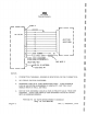
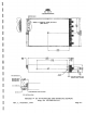
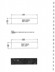
2.7
KA
48
INSTALLAiiON
The
KA
4a
antenna
is
a
vertical
quarter
wave
di
pol
e
designed
for
optimum
performance
at
the
transponder
operating
frequency.
When
making
the
antenna
insta
ll
ation
guidelines
should
be
taken
from
an
investigation
of
proven
s
atisfactory
transponder
and
DME
antenna
installations.
....:
.NOTE-
A . 380
inch
clearance
hole
is
required.
The
antenna
should
be
kept
clean.
If
left
dirty
(oil
covered)
the
range
of
the
transponder
may
be
affected.
2.8
LOCATION
CONSIDERATIONS
1.
2.
Page
2-4
The
antenna
shou
ld
be
well
removed
from
any
projections,
the
engine(
s)
and
propeller(
s).
The
antenna
should
be
mounted
on
a
bottom
surface
that
will
be
level
in
normal
aircraft
flight
attitudes.
Rev.
1,
December,
197
.2