
Installation manual


~
KING
KT
76/78
TRANSPONDI
!~
R
...
--
/
'",
I 0 0 \
..)
fi
_
_g
)
--;
· \ a
14a
'
"1--..T
/
.....
__
.,..
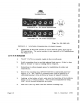
F:IGURE
2-lA
+13. 75VDC
OPERATION
.,.-
...
'
/tt~!l
',
I 0 0 \
j . .
--
\ . o e /
' ...
...
-
FIGURE
2-1B
+
27.
5VDC
OPERATION
(Dwg.
No.
696-3002-00)
l
<'
IGUH.E
2-1
VOLTAG
E
CHANGEOVER
O.F
FRONT
PAN
E L
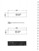
3}
Install
the
10
ohm
55W
resistor
in
s
eries
with
the
power
input
pin
for
28V
operation.
The
series
resistor
is
not
required
in
14V
installations.
See
Figure
2-3.
2.5
KT
76/78
INSTALLATION
Page
2-2
1.
The
KT
76/78
are
mounted
rigidly
in
the
aircraft
panel.
2.
Avoid
mounting
clo
s e
to
any
high
external
heat
source,
if
this
is
done
then
no
blower
or
ram
air
cooling
will
be
required.
3.
RemembEr
to
allow
adequate
space
for
installat
i
on
of
cables
and
connecto
~
s.
4.
Secure
the
mounting
tray
KPN
047
-
2439-02
to
instrument
panel
oer
Figure
2
-4.
The
rearward
mounting
holes
must
be
attached
to
a
structua
l.
·
member
of
the
airframe
by
means
of
support
brackets.
5.
6.
Looking
at
the
bottom
of
unit,
mak
e
sure
the
front
lobe
of
the
holddown
device
is
in
a
vertical
position.
This
can
be
accomplished
by
using
3/32n
Allen
wrench
through
the
face
plate.
Slide
un
i.
t
into
tray
until
front
lobe
touches
mounting
tray.
Rev.
1,
December
1912
0
0
0
0
0