
Installation manual


0
0
0
0
0
0
0
0
0
0
0
.0
D
0
0
0
0
D
2.1
GENERAL
~
KING
KT
76/78
T :RANSPOND.gR
SECTION
II
INSTALLATION
Installation
of
the
KT
76/78
will
differ
according
to
equipment
location
and
other
factors.
Cable
harnesses
wil
l
be
fabricated
by
the
installing
agency
to
fit
these
various
require-
ments.
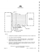
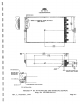
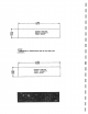
This
section
contains
interconnect
diagrams,
mounting
dimensions
and
infor-
mation
pertaining
to
installation.
2.2
UNPACKING
AND
INSPECTING
·
EQUIPMENT
Exercise
extreme
care
when
unpacking
the
equipment.
Make
a
visual
inspection
of
the
unit
for
evidence
of
damage
incurr
ed
during
shipment.
If
a
claim
for
damage
is
to
be
made,
save
the
shipping
container
to
substantiate
the
claim.
The
claim
should
be
promptly
filed
with
the
transportation
company.
When
equipment
has
been
removed,
place
in
the
shipping
container
all
packing,
bracing,
and
filler
used
in
the
original
pack-
ing.
Save
the
packing
material
for
use
in
unit
storage
or
reshipment.
2.3
INSTALLATION
PROCEDURES
Listed
below
are
factors
and
suggestions
to
consider
before
installing
your
KT
76/78.
Close
adherence
to
these
suggestions
will
assure
more
satisfactory
performance
from
your
equipment.
Also
note
the
following
instructions
for
voltage
changeover
in
the
KT
76/78.
2.4
VOLTAGE
CHANGE
OVER
INSTRUCTIONS
The
KT
76/78
may
be
ordered
from
the
factory
for
.14
volt
or
28
volt
operation.
To
con-
vert
a 14V
unit
to
28V
operation
use
voltage
change
over
kit
KPN
050-1247-00.
To
con-
vert
a 28V
unit
to
14V
operation
use
voltage
change
overkit
KPN
050-1247-01.
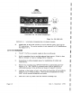
1)
:Remove
the
front
panel
of
the
radio,
JTigure
2-1
shows
the
front
of
the
switch
board.
·
In
the
lower
rigb.t
corner
are
located
six
jumper
pins.
Ji..,igure 2
-la
shows
the
proper
jumper
connection
for
14 VDC
operation
while
F_
igure
2-lb
shows
the
connections
for
28VDC
operation
· 2)
Lamp
Voltage
Tag
must
correspond
to
voltage
used.
The
tag
is
located
oh
rear
of
unit
and
is
supplied
with
Voltage
Changeover
Kit.
..Page
2-l