
Manual
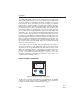
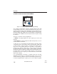
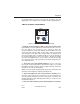
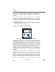
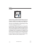
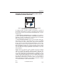
Table Of Contents
- TITLE PAGE
- TABLE OF CONTENTS
- INTRODUCTION
- SECTION I
- CHARACTERISTICS OF HF SSB
- ACRONYMS AND DEFINITIONS
- REFERENCES
- HF SSB COMMUNICATIONS
- FREQUENCY
- SKYWAVE PROPAGATION - WHICH FREQUENCY TO
- WHY SINGLE SIDEBAND IS IMPORTANT IN HF
- AMPLITUDE MODULATION (AM)
- SINGLE SIDEBAND OPERATION
- SINGLE SIDEBAND (SSB)
- SUPPRESSED CARRIER VS. REDUCED CARRIER
- SIMPLEX AND SEMI-DUPLEX OPERATION
- AUTOMATIC LINK ESTABLISHMENT (ALE)
- FUNCTIONS OF HF RADIO AUTOMATION
- HOW ALE ASSURES THAT THE BEST COMMUNICA-TIONS
- CHARACTERISTICS OF HF SSB
- SECTION II
- SECTION III
- SECTION IV
- SECTION V
- SECTION VI
- SECTION VII
- ITU MARITIME RADIOTELEPHONE STATIONS
- DESCRIPTION OF SERVICES
- AT&T HIGH SEAS RADIOTELEPHONE SERVICE
- AT & T COAST STATION COVERAGE MAP
- COAST STATION COVERAGE & INFORMATION
- AIRCRAFT REGISTRATION
- OPERATING PROCEDURES FOR USING THE HIGH SEAS RADIOTELEPHONE NETWORK
- AT&T HIGH SEAS COAST STATIONS
- MOBILE MARINE RADIO, INC.
- WORLDWIDE LISTING OF PUBLIC CORRESPONDENCE STATIONS
- MARITIME RADIOTELEPHONE CHANNEL DESIGNATIONS
- SECTION VIII
- SECTION IX
- SECTION X
- SECTION XI
- SECTION XII
- SECTION XIII
MARITIME RADIOTELEPHONE NETWORK (PUBLIC CORRE-
SPONDENCE) CHANNEL OPERATION
As explained earlier, all 245 ITU public correspondence channels in
the maritime radiotelephone network are programmed permanently in
the electronic memory of the KFS 594 Control Display Unit. To oper-
ate this mode:
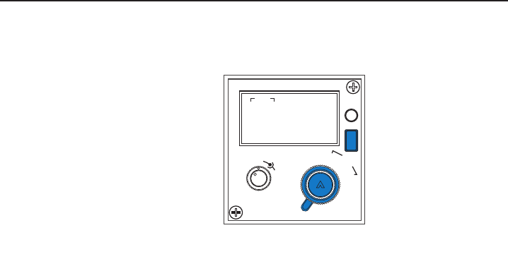
1. Select the A3J or A3A mode.Move the MODE selector switch to
the A3J or A3A position. Most maritime radiotelephone (public corre-
spondence) stations, including those of the Bell System and Mobile
Marine Radio System, work in the A3J format.
2. Select the desired channel.An ITU channel number will be dis-
played in the lower right of the display when you move the MODE
selector switch to the A3J or A3A position. If the channel number isn’t
the one desired, select another by first unstowing the “cursor” (flash-
ing digit) by pressing the Frequency/Channel control knob. Press this
knob enough times to move the “cursor” to the first “cursor” position
in the ITU channel number to be changed. (This will be 6, 8, 12, 16,
etc.) Next twist the Frequency/Channel control knob to select the
desired number.
NOTE: There are only two “cursor” positions for the ITU channel
number. The “hundreds” position controls the “thousands” position
also. For example, if the displayed channel number is 1204 the “cur-
sor” could be moved to the “12” but not to the “1”. With the “cursor”
on the “12”, turning the Frequency/Channel control knob one step
counter-clockwise will change the “12” to an “8” while another step in
the same direction would change the “8” to a “6”. By referring to
theMaritime Radiotelephone Network (Public Correspondence)
Channel Operation list in table 7-13 you will see that these changes
are consistent with the actual channel numbers.
Operation
3-71
KHF 950/990 Pilots Guide
Rev. 0
Dec/96
1
S
T
O
HF
OFF
TELAM
USB
LSB
A3J
A3A
VOL
SQ
401
19 - 12
CH
M
H
Z
T
K
H
Z
Figure 3-83 Maritime Radiotelephone Network (Public
Correspondence) Channel Operation