
User's Manual

62
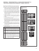
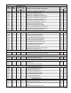
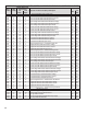
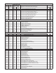
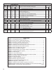
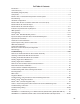
APPENDIX B: J1939 SPN AND FMI CODES AND THEIR BENDIX
®
BLINK CODE EQUIVALENTS
SPN
(J1939)
FMI
(J1939)
Bendix
®
Blink Code
Equivalent(s)
Diagnostic Trouble Code (DTC) Description
Lamp Status
(1st
Digit)
(2nd
Digit)
ABS
ATC/
ESP
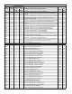
Lateral Acceleration Sensor DTCs
1809 2 23 1 LAS Signal of Range
‑ ON
1809 2 23 3 LAS Static Calibration Error
‑ ON
1809 2 23 4 LAS Long Term Calibration Error
‑ ON
1809 2 23 5 LAS Plausibility Error (Inside Model Based Limits)
‑ ON
1809 2 23 6 LAS Plausibility Error (Outside Model Based Limits)
‑ ON
1809 13 22 15
YRS‑ SAS Signal Cross‑Check Incomplete ‑ ON
1809 13 23 2 LAS Calibration in Progress
‑ ON
Miscellaneous
2011 31 11 26 ABS ECU CAN Address Conict ON
‑
2051 31 11 27 TPMS ECU CAN Address Conict ‑ TPMS INDICATOR LAMP ON ‑ ‑
HS/HSA Hill Start Feature DTCs
2622 2 12 24 HSA lamp Open Circuit or Shorted to GND ON
‑
2622 3 12 26 HSA valve: Solenoid Shorted to Voltage ON ‑
2622 3 12 31 HSA lamp Shorted to Voltage ON ON
2622 4 12 25 HSA valve: Solenoid Shorted to Ground
‑ ‑
2622 5 12 33 HSA valve: Solenoid Open Circuit ‑ ‑
Bendix
®
eTrac
™
DTCs
2984 3 12 34 Bendix
®
eTrac
™
Solenoid Shorted to Voltage ‑ ON
2984 4 12 35 Bendix eTrac Solenoid Shorted to Ground
‑ ON
Figures Used
Figure 1 - Bendix
®
ESP
®
EC‑80
™
Controller ....................................................................1
Figure 2 - Bendix
®
WS‑24
™
Wheel Speed Sensors .........................................................3
Figure 3 - Example Of A Bendix
®
M‑40X
™
Modulator .....................................................3
Figure 4 - Examples Of Steering Angle Sensors ............................................................3
Figure 5 - Yaw And Brake Demand/Load Sensors ..........................................................4
Figure 6 - Additional Valves Necessary For The Hill Start Feature .................................4
Figure 7 - Bendix ESP EC‑80 Controller Features ..........................................................5
Figure 8 - Power Line Without PLC Signal ......................................................................5
Figure 9 - Power Line With PLC Signal ...........................................................................5
Figure 10 - Bendix ESP EC‑80 Controller Indicator Lamp Behavior ...............................8
Figure 11 - Vehicle Orientation (Typical) .........................................................................9
Figure 12 - RSP Example .............................................................................................. 12
Figure 13 - Yaw Control Example ..................................................................................12
Figure 14 - Typical Vehicle Diagnostic Connector Locations (J1939) ...........................21
Figure 15 - Example Of Blink Code Message ...............................................................21
Figure 16 - Diagnostic Modes........................................................................................22
Figure 17 - System Conguration Check .......................................................................23
Figure 18 - Bendix
®
ACom
®
Diagnostics .......................................................................24
Figure 19 - The Bendix
®
Remote Diagnostic Unit..........................................................24
Figure 20 - Diagnostic Trouble Codes ........................................................................... 25
Figure 21 - Bendix EC‑80 Controller Component Connectors ......................................50
Figure 22 - WS‑24 Wheel Speed Sensor Installation (S‑Cam And Air Disc Brake) ...... 51
Figures 23 & 24 - Troubleshooting: Wiring Schematics ...........................................52‑53