
User's Manual

55
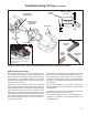
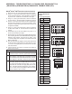
APPENDIX A: TROUBLESHOOTING A 12-7 BLINK CODE, EQUIVALENT TO A
(SID-93 FMI-4) (SPN-0802 FMI-04) DIAGNOSTIC TROUBLE CODE (DTC)
Bendix
®
EC-80
™
ESP
®
Electronic Control Unit (ECU)
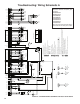
1) Remove the X1, X2, X3 and X4 connectors from the ECU.
2) Using X1‑1 as the ground connection, check for resistance
for the entire X2 connector. There should be no resistance
to ground found. Please ll out worksheet on this page.
3) Using X1‑1 as the ground connection, check for resistance
for X1‑4 and X1‑5. There should be no resistance to ground.
4) Using X1‑1 as the ground connection, check for resistance for
X3‑4, X3‑6, X3‑7, X3‑9, X3‑10, X3‑13, X3‑3 and X3‑5. There
should be no resistance to ground. (Even if the vehicle is not
congured for 6S/6M).
5) Using X1‑1 as the ground connection, check for resistance
for X4‑6, X4‑9 and X4‑12. There should be no resistance to
ground.
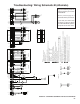
6) Troubleshoot any pin that has resistance to ground. If no
issues are found continue to step 7.
7) Reconnect the X1 connector only and apply IGN power to the
ECU and using the DTC screen of Bendix
®
ACom
®
Diagnostic
Software, clear all DTCs. Re‑check for any DTCs. If the
12‑7 DTC is still present, the problem is the Traction Solenoid
Wiring or Solenoid.
8) If the 12‑7 DTC does not reappear, remove power and connect
the X2 connector, reapply power, then clear all DTCs. If the
12‑7 DTC is no longer present, connect the X3 connector
and clear all DTCs.
9) If at this point the 12‑7 DTC is not present, the problem is
with the X4 connector.
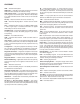
For Peterbilt
®
& Kenworth
®
Trucks Only:
10)
Clear all DTCs. If the 12‑7 DTC reappears, the issue is
on the X4 connector. Otherwise, proceed to the next step.
11) Disconnect all modulators and the traction solenoid.
Clear all DTCs. If the DTC does not reappear, connect
one modulator and Traction Solenoid at a time, until the
DTC reappears. Otherwise, continue to the next step.
12) Make sure all modulators and the traction solenoid are
connected. Disconnect the ABS bulkhead connector at
the engine (top‑left side) and remove Pins 1, 2, 11 &12.
Reconnect the connector and apply IGN power to the
ECU. Using Bendix ACom Diagnostics, clear all DTCs.
If the 12‑7 DTC returns, the problem is either the wiring
harness inside the cab or the ECU.
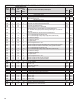
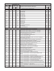
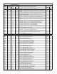
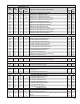
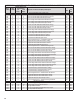
Record Resistances
Below:
X1-1 for ground point
X1 Pin Resistance
X1‑4
X1‑5
X2 Pin Resistance
X2‑1
X2‑2
X2‑3
X2‑4
X2‑5
X2‑6
X2‑7
X2‑8
X2‑9
X2‑10
X2‑11
X2‑12
X2‑13
X2‑14
X2‑15
X2‑16
X2‑17
X2‑18
X3 Pin Resistance
X3‑4
X3‑5
X3‑6
X3‑7
X3‑8
X3‑9
X3‑10
X3‑13
X4 Pin Resistance
X4‑6
X4‑9
X4‑12
4