
User's Manual


5
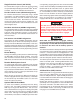
ABS
Off-
Road
ATC
ATC
Mud/Snow
Blink
Codes
ESP/
RSP
HSA
Hill Start
Aid Feature
Bendix
®
eTrac
™
system*
Input
Voltage
PLC
Modu-
lators
(PMVs)
Retarder
Relay
Sensors
Serial
Communication
J1939
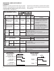
Optional Optional Optional 12/24 4/5/6 4/6
*
For information about the Bendix
®
eTrac
™
automated air suspension transfer system, see SD‑13‑21021
FIGURE 7 - BENDIX
®
ESP
®
EC‑80
™
CONTROLLER FEATURES
BENDIX
®
ESP
®
EC-80
™
CONTROLLERS USE
POWER LINE CARRIER (PLC)
All new towing vehicles built since March 1, 2001, have had
an in‑cab trailer ABS Indicator Lamp installed.
Trailers built since March 1, 2001, transmit the status of
the trailer ABS over the power line (the blue wire of the
J560 connector) to the tractor using a Power Line Carrier
(PLC) signal. See Figures 8 and 9. Typically the signal is
broadcast by the trailer ABS Electronic Control Unit (ECU).
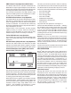
FIGURE 8 - POWER LINE WITHOUT PLC SIGNAL
FIGURE 9 - POWER LINE WITH PLC SIGNAL
The application of PLC technology for the heavy vehicle
industry in North America is known as “PLC4Trucks.”
The Bendix
®
ESP
®
EC‑80
™
Controller supports PLC
communications in accordance with SAE J2497.
PLC SIGNAL
An oscilloscope can be used to measure or identify the
presence of a PLC signal on the power line. The PLC
signal is an amplitude and frequency‑modulated signal.
Depending on the ltering and load on the power line,
the PLC signal amplitude can range from 5.0 mVp‑p to
7. 05 Vp ‑ p.
Suggested oscilloscope settings are AC coupling, with one
volt/div, 100 µsec/div. The signal should be measured at
the ignition power input of the Bendix EC‑80 Controller.
Note: An ABS trailer equipped with PLC, or a PLC
diagnostic tool, must be connected to the vehicle in order
to generate a PLC signal on the power line.
BENDIX ESP EC-80 CONTROLLER INPUTS
Battery and Ignition Inputs
The Bendix ESP EC‑80 Controller operates at a nominal
supply voltage of 12 or 24 volts, depending on the ECU.
The battery input is connected through a 30 amp fuse
directly to the battery.
The ignition input is applied by the ignition switch circuit
through a 5 amp fuse.
Ground Input
The Bendix ESP EC‑80 Controller supports one ground
input. See pages 52 and 53 for wiring system schematics.
ABS Indicator Lamp Ground Input
The Bendix ESP EC‑80 Controller requires a second
ground input (X1‑12) for the ABS indicator lamp. The X1
wire harness connector contains an ABS indicator lamp
interlock (X1‑15), which shorts the ABS indicator lamp
circuit (X1‑18) to ground if the connector is removed from
the ECU.
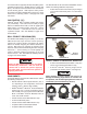
Bendix
®
WS-24
™
Wheel Speed Sensors
Wheel speed data is provided to the Bendix ESP EC‑80
Controller from the Bendix
®
WS‑24
™
wheel speed sensor
(see Figure 2). Vehicles have an exciter ring (or “tone
ring”) as part of the wheel assembly. As the wheel
turns, the teeth of the exciter ring pass the wheel speed
sensor, generating an AC signal. The Bendix ESP EC‑80
Controller receives the AC signal, which varies in voltage
and frequency as the wheel speed changes.
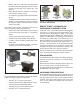
Vehicle axle configurations determine the number of
Bendix WS‑24 wheel speed sensors that must be used.
A vehicle with a single rear axle requires four wheel speed
sensors. Vehicles with two rear axles can utilize six wheel
speed sensors for optimal performance.