
User's Manual

43
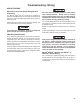
Troubleshooting Diagnostic Trouble Codes (DTCs):
Brake Demand/Load Sensors
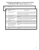
Brake Demand/Load Sensor Tests
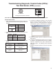
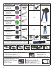
1. Verify continuity between the ECU and the pressure
sensor power and ground.
Power and Ground Input Test Measurement
B = Power Input X4 ‑ 4 Power
A = Ground Input X4 ‑ 1 Common
2. Verify wiring between the Load Sensor and the ECU.
Load Sensor
Wire Harness
Terminal
ECU Wire Harness
Terminal
Measurement
C
X4 ‑ 2 Brake Demand
Sensor (primary brake circuit)
Verify Continuity
X4 ‑ 5 Brake Demand Sensor
(secondary brake circuit)
Verify Continuity
X4 ‑ 3 Load Sensor Verify Continuity
Looking into wire
harness connector
3. Verify wiring between the Load Sensor and power/
ground.
Load Sensor
Harness Terminal
Measurement
C to Voltage & Ground Verify open circuit (no continuity)
4. To perform a calibration procedure of the Brake Demand
Sensor(s), ensure that the air system is fully charged.
Apply ignition power, and wait 30 seconds. Perform
a full application of the service brake and hold for 5
seconds. Release the service brake.
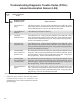
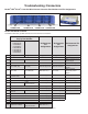
5. To test the Brake Demand Sensor and/or the Load
Sensor, Bendix
®
ACom
®
Diagnostic Software V6.7.2.5
or higher is required. Using the program, select the
“Component Test” option, followed by the “ESP Test”
option. The following screen should be displayed.
6. Follow the prompts to test the Brake Demand Sensor(s)
and/or the Load Sensor.
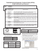
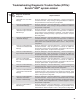
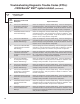
1st. Blink
Code
24
Location:
Brake Demand/
Load Sensor
2nd.
Blink
Code
Diagnostic Trouble
Code Description
Repair Information
1 PS1 Open or
Shorted
Check wiring between Brake Demand Sensor (primary brake circuit) and
Electronic Control Unit (ECU). Verify operation of pressure sensor.
2 PS2 Open or
Shorted
Check wiring between Brake Demand Sensor (secondary brake circuit) and ECU.
Verify operation of pressure sensor.
3 PS3 Open or
Shorted
Check wiring between Load Sensor and ECU. Verify operation of pressure sensor.
4 PS1/2
Plausibility Error
ECU has detected an invalid pressure sensor signal from one of the Brake
Demand Sensors.
5 PS Supply
Voltage Error
Incorrect supply voltage to the sensors. Verify the proper voltage at sensor
connectors. Verify wiring between the ECU and the sensors. Verify the proper
output voltage from the ECU (Specically, ensure that X4‑4 PS_SPL is not
shorted to ground).
6 PS Not
Calibrated
Perform static sensor calibration procedure. (NOTE: When replacing an ECU,
this DTC may occur.)
7 PS Error Verify operation of pressure sensor.
8 PS Supply
Voltage Error
Incorrect supply voltage to sensors. Verify the proper voltage at sensor connectors.
Verify wiring between ECU and the sensors. Verify the proper output voltage from ECU.
9 PS Not
Congured
Check for presence of pressure sensors. Make sure ESP is enabled.