
User's Manual

41
Troubleshooting Diagnostic Trouble Codes (DTCs):
Yaw Rate Sensor (YRS) (continued)
Yaw Rate Sensor Tests
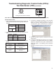
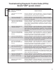
1. Verify continuity between the Electronic Control Unit
(ECU) and the Yaw Rate Sensor (typically YAS‑70 or
YAS‑60).
Connector Pin Function
YRS
2 Voltage Input
1 Ground Input
ECU
12 Way
X4
11 Power
10 Common
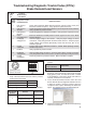
2. Verify wiring between the Yaw Rate Sensor and the
ECU.
YRS Wire
Harness
Terminal
ECU Wire
Harness
Terminal
Measurement
4 7 Verify Continuity
3 8 Verify Continuity
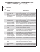
3. Verify wiring between the Yaw Rate Sensor and power/
ground.
YRS Wire Harness
Terminal
Measurement
4 to Voltage &
Ground
Verify open circuit (no
continuity)
3 to Voltage &
Ground
Verify open circuit (no
continuity)
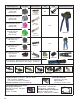
Looking into wire harness connector
Yaw Connector
(Note: When checking for voltage at YAW/LAS & SAS, the voltage will only be present momentarily at key ON.).
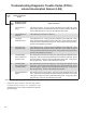
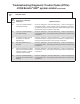
4. To perform a calibration procedure of the Yaw Rate
Sensor, ACom
®
Diagnostic Software V6.7.2.5 (or
higher) is required. Using the program, select the
“Configuration” option, followed by the “Calibrate”
option. The following screen should be displayed.
5. Follow the prompts to perform a calibration of the Yaw
Rate Sensor.
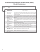
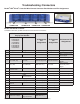
6. To test the Yaw Rate Sensor, ACom V6.7.2.5, or higher,
is required. Using Bendix ACom V6.7.2.5 or higher,
select the “Component Test” option, followed by the
“ESP Test” option. The following screen should be
displayed.
7. Follow the prompts to perform a test of the Yaw Rate
Sensor.