
User's Manual

34
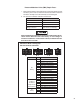
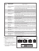
1st. Blink
Code 12
Location:
Miscellaneous
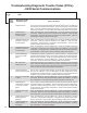
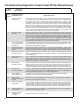
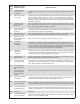
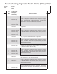
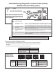
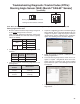
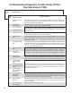
Troubleshooting Diagnostic Trouble Codes (DTCs): Miscellaneous
2nd.
Blink
Code
Diagnostic Trouble
Code Description
Repair Information
1 Stop Lamp Switch
Not Detected
The Electronic Control Unit (ECU) has not detected the presence of the stop lamp switch
since ignition power was applied (note that stop lamp switch input may be applied to
the Bendix
®
ESP
®
EC‑80
™
Controller using either hard‑wire input or J1939). Apply
and release service brake. Check for brake switch input into ECU (see system wiring
schematic). With service brake released, check for presence of the stop lamp bulb.
With service brake applied, verify system voltage is now present at the stop lamp switch
input to the ECU. Check for damaged wiring between ECU, stop lamp switch and bulb.
Check for corroded or damaged connectors. Check for damaged or reversed J1939
wiring. Check for corroded or damaged connectors on J1939 link. Verify the presence
of engine ECU on the J1939 link. Verify the ECU conguration.
2 Stop Lamp Switch
Defective
Apply and release service brake. Check for brake switch input into ECU (see system
wiring schematic). With service brake released, check for presence of the stop lamp bulb.
With service brake applied, verify system voltage is now present at the stop lamp switch
input to the ECU. Check for damaged wiring between ECU, stop lamp switch and bulb.
Check for corroded or damaged connectors. Check for damaged or reversed J1939
wiring. Check for corroded or damaged connectors on J1939 link. Verify the presence
of engine ECU on the J1939 link. Verify the ECU conguration.
3 ATC or ESP Disabled
or Dynamometer Test
Mode Active
ATC or ESP is disabled. ECU has been placed in the Dynamometer Test Mode by either
the diagnostic Blink Code Switch or a hand‑held or PC‑based diagnostic tool. Clear
DTCs to exit Dynamometer Test Mode.
4 Retarder Relay Open
Circuit or Shorted to
Ground
Verify vehicle contains a retarder relay. Verify the ECU conguration. Check wiring
between ECU and retarder relay. Verify no continuity between retarder disable output of
Bendix ESP EC‑80 Controller and ground. Verify condition and wiring of the retarder relay.
5 Retarder Relay Circuit
Shorted to Voltage
Check wiring between ECU and retarder relay. Verify no continuity between retarder
disable output of Bendix ESP EC‑80 Controller and voltage. Verify condition and wiring
of the retarder relay.
6 ABS Indicator Lamp
Circuit DTC
Check operation of diagnostic Blink Code Switch. Check wiring of diagnostic Blink Code
Switch (verify ABS wire is not grounded where used) and ABS Indicator Lamp. Verify
ABS Indicator Lamp ground input. On some vehicles with multi‑plex dashes, the ground
wire may not be present - see ECU 19 DTC.
7 PMV Common
Shorted to Ground
Verify no continuity between the Release, Hold and CMN of all Pressure Modulator Valves
(PMVs), Traction Control Valve (TCV), HSA, Diff Lock Solenoid and ground. Check for
corroded/damaged wiring or connectors between the ECU and CMN of all PMVs, TCV,
and Diff Lock Solenoid. See the extended troubleshooting for this code in Appendix A.
8 PMV Common
Shorted to Voltage
Verify no continuity between the Release, Hold and CMN of all PMVs, TCV, HSA, Diff
Lock Solenoid and voltage. Check for corroded/damaged wiring or connectors between
the ECU and CMN of all PMVs, TCV, and Diff Lock Solenoid.
9 ATC Disabled to
Prevent Brake Fade
The Bendix
®
ATC (Automatic Traction Control) system is temporarily disabled to
prevent excessive heating of the foundation brakes.
11 Wheel Speed
Sensors Reversed on
an Axle
Sensors are reversed (left to right) on one of the axles. Verify the proper installation,
connection, and wiring of the sensors.
14 Sensor CAN Supply
Voltage Error
Incorrect supply voltage for the Steering Angle Sensor (SAS) and the Yaw Rate sensor.
Verify the proper voltage at the sensor connectors. Verify the wiring between the ECU
and the sensors. Verify the proper output voltage from ECU. Note: When checking for
voltage at YAW/LAS & SAS, the voltage will only be present momentarily at key ON.
17 ABS disabled due to
off‑road mode
The ABS indicator lamp will be ashing, indicating the ECU is in the off‑road ABS mode.
Remove and re‑apply ignition power.
19 Maximum number
of PMV cycles
exceeded
Replace all PMV valves and clear the DTC.