
User's Manual

33
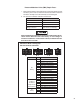
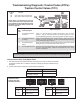
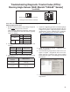
Cab-mount ECU:
Looking into wire harness connector
J1939 Troubleshooting Tests:
1. Take all measurements at ECU harness
connector.
2. Check for damaged or reversed J1939
wiring.
3. Check for corroded or damaged wiring
connector problems such as (opens or
shorts to voltage or ground).
4. Check for other J1939 devices which
may be loading down (inhibiting) J1939
communication.
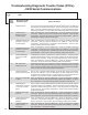
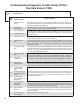
X4
2nd.
Blink
Code
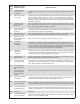
Diagnostic Trouble
Code Description
Repair Information
15 J1939 Electronic Engine
Controller 3 Time‑out or
Invalid Signal
There is loss of communications between the Bendix
®
ESP
®
EC‑80
™
Controller and
the engine Electronic Control Unit (ECU) over the J1939 link. Check for damaged
or reversed J1939 wiring. Check for corroded or damaged connectors. Verify the
presence of engine ECU on the J1939 link. Verify the ECU conguration. Check
for other devices inhibiting J1939 communications.
16 J1939 Electronic
Transmission Controller
2 Time‑out
There is loss of communications between the Bendix EC‑80 Controller and the
transmission ECU over the J1939 link. Check for damaged or reversed J1939 wiring.
Check for corroded or damaged connectors. Verify the presence of engine ECU
on the J1939 link. Verify the ECU conguration. Check for other devices inhibiting
J1939 communications..
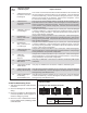
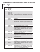
20 J1939 EAC1 Time‑out
or Invalid Signal
Verify 60 ohms of resistance between X1 pin 7 and X1 pin 8. Check for damaged
or reversed J1939 wiring. Check for damaged or corroded connectors. Verify that
the message is being transmitted. Verify data for Electronic Axle Controller 1 is
correct. Verify the ECU conguration.
21 CAN Message
CGW_C1 Time‑out or
invalid signal
Verify 60 ohms of resistance between X1 pin 7 and X1 pin 8. Check for damaged or
reversed J1939 wiring. Check for damaged or corroded connectors. Verify that the
message is being transmitted. Verify that the data for differential lock(s) is correct.
Verify the ECU conguration.
22 CAN Message
ASC1_CLCS Time‑out
or invalid signal
Verify 60 ohms of resistance between X1 pin 7 and X1 pin 8. Check for damaged
or reversed J1939 wiring. Check for damaged or corroded connectors. Verify that
the message is being transmitted. Verify that the data for Air Suspension Control 1
is correct. Verify the ECU conguration.
23 J1939 CCVS Time‑out
or Invalid Signal
Verify 60 ohms of resistance between X1 pin 7 and X1 pin 8. Check for damaged or
reversed J1939 wiring. Check for damaged or corroded connectors. Verify message
is being transmitted. Verify the ECU conguration.
24 J1939 TCO
(Tachograph)
Time‑out
Verify 60 ohms of resistance between X1 pin 7 and X1 pin 8. Check for damaged or
reversed J1939 wiring. Check for damaged or corroded connectors. Verify message
is being transmitted. Verify the ECU conguration.
26 J1939 Address Conict
ABS Address
Verify only one ABS ECU is connected on J1939 bus, broadcasting OBh (equals
13 decimal).
27 J1939 Address Conict
TPMS Address
Verify only one TPMS ECU is connected on J1939 bus, broadcasting 33h.
28 J1939 Proprietary XBR
Message Out of Range
Verify 60 ohms of resistance between X1 pin 7 and X1 pin 8. Check for damaged
or reversed J1939 wiring. Check for damaged or corroded connectors. Check for
messages being transmitted/received.
29 J1939 CAN Messages
Are Not Being
Transmitted/Received
Verify 60 ohms of resistance between X1 pin 7 and X1 pin 8. Check for damaged
or reversed J1939 wiring. Check for damaged or corroded connectors. Check for
messages being transmitted/received.
Connector Pin J1939
X1
18 Way
7 J1939 Low
8 J1939 High