
User's Manual

31
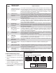
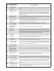
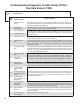
Pressure Modulator Valve (PMV) Repair Tests:
1. Take all measurements at the Electronic Control Unit (ECU) harness
connector pins in order to check wire harness and PMV. Probe the
connector carefully so that the terminals are not damaged.
2. The pressure modulator resistance should read:
Location Measurement
Release to Common 4.9 to 5.5 Ohms
Hold to Common 4.9 to 5.5 Ohms
Release to Hold 9.8 to 11.0 Ohms
Release, Hold, Common to
Voltage or Ground
Open Circuit (no continuity)
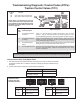
When troubleshooting modulator Diagnostic Trouble Codes (DTCs),
check inactive DTCs and the event history for over-voltage or
excessive noise DTCs. If one of these is found, troubleshoot these
DTCs rst before the PMV.
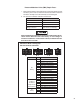
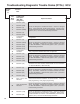
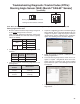
Cab-mount ECU: Looking into
the wire harness connector
4
Connector Pin PMV Location
X2
18 Way
1 Left Steer Axle Hold
2 Left Steer Axle Release
3 Left Steer Axle Common
4 Right Steer Axle Hold
6 Right Steer Axle Common
7 Right Steer Axle Release
9 Right Drive Axle Common
10 Right Drive Axle Hold
13 Right Drive Axle Release
12 Left Drive Axle Common
16 Left Drive Axle Hold
17 Left Drive Axle Release
X3
15 Way (if
the ECU is
congured for
6 modulators)
4 Left Additional Axle Hold
6 Left Additional Axle Common
7 Left Additional Axle Release
9 Right Additional Axle Common
10 Right Additional Axle Hold
13 Right Additional Axle Release
X4
12 Way
6 Trailer PMV Hold
9 Trailer PMV Release
12 Trailer PMV Common