
User's Manual

28
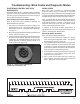
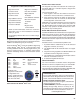
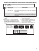
Cab-mount ECU: Looking into
the wire harness connector
X4
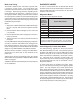
Connector Pin
Wheel Speed Sensor
Location
X1
18 Way
10 Right Drive Axle (+)
11
Right Drive Axle (‑)
X2
18 Way
5 Left Steer Axle (+)
8
Left Steer Axle (‑)
11 Right Steer Axle (+)
14
Right Steer Axle (‑)
15 Left Drive Axle (+)
18
Left Drive Axle (‑)
X3
15 Way
(if ECU is
congured for
6 sensors)
11 Left Additional Axle (+)
14
Left Additional Axle (‑)
12 Right Additional Axle (+)
15
Right Additional Axle (‑)
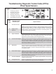
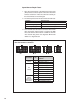
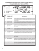
Speed Sensor Repair Tests:
1. Take all measurements at the Electronic Control Unit
(ECU) harness connector pins in order to the check wire
harness and sensor. Probe the connector carefully so
that the terminals are not damaged.
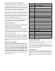
2. The wheel speed sensor measurements should read:
Location Measurement
Sensor
1500 ‑ 2500 Ohms
Sensor to voltage or ground Open Circuit (no continuity)
Sensor output voltage >0.25 of VAC sensor output at ~ 0.5 revs/sec.
3. Clear the DTC after the issue is corrected. The sensor
DTC will remain until the power is cycled to the ABS
ECU and vehicle is driven above 15 MPH or the DTC
was cleared using either the diagnostic Blink Code
Switch or a diagnostic tool.