
User's Manual

27
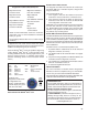
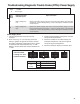
Troubleshooting Diagnostic Trouble Codes (DTCs):
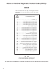
Wheel Speed Sensors
2 Left Steer Axle Sensor
3 Right Steer Axle Sensor
4 Left Drive Axle Sensor
5 Right Drive Axle Sensor
14 Left Additional Axle Sensor
15 Right Additional Axle Sensor
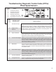
1st. Blink
Code
Location
2nd.
Blink
Code
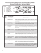
Diagnostic Trouble
Code Description
Repair Information
1 Excessive Air Gap
Adjust the sensor to contact the exciter ring. Rotate the wheel and verify a minimum
of 0.25 VAC sensor output at ~ 0.5 RPS. Verify the condition of the sensor head.
Verify the mounting of the exciter ring and condition of the teeth. Verify the proper
bearing end‑play. Verify the condition and retention of the clamping sleeve. Verify
the sensor lead routing and clamping.
2 Output Low at
Drive‑off
3 Open or Shorted
Verify 1500 – 2500 ohms is found across the sensor leads. Verify no continuity between
the sensor leads and ground or voltage. Verify no continuity between the sensor leads
and the other sensors. Check for corroded/damaged wiring or connectors between
the Electronic Control Unit (ECU) and the wheel speed sensor.
4 Loss of Sensor Signal
Adjust the sensor to contact the exciter ring. Rotate the wheel and verify a minimum
of 0.25 VAC sensor output at ~ 0.5 RPS. Verify the condition of sensor head. Verify
the mounting of the exciter ring and condition of the teeth. Verify the proper bearing
end‑play. Verify the condition and retention of the clamping sleeve. Verify the sensor
lead routing and clamping. Check for corroded/damaged wiring or connectors between
the ECU and the wheel speed sensor.
5 Wheel End
Verify the mounting of exciter ring and the condition of teeth. Verify the proper bearing
end‑play. Verify the condition and retention of the clamping sleeve. Verify the sensor
lead routing and clamping. Check the mechanical function of brake. Check for kinked
or restricted air hoses.
6 Erratic Sensor Signal
Adjust the sensor to contact the exciter ring. Rotate the wheel and verify a minimum
of 0.25 VAC sensor output at ~ 0.5 RPS. Verify the condition of sensor head. Verify
the mounting of the exciter ring and condition of the teeth. Verify the proper bearing
end‑play. Verify the condition and retention of the clamping sleeve. Verify the sensor
lead routing and clamping. Check for corroded/damaged wiring or connectors between
the ECU and the wheel speed sensor.
7 Tire Size Calibration
Verify the correct tire size as desired. Verify the proper tire ination. Verify the correct
number of exciter ring teeth.
10 Conguration Error
The ECU is congured for four sensors, but it has detected the presence of additional
sensors. Verify the sensor wiring and the ECU conguration.