
User's Manual

25
Typical Combination
Diagnostic Trouble Codes (DTCs) are:
• Right steer sensor
• Left steer sensor
• Right drive sensor
• Left drive sensor
• Right additional sensor
• Left additional sensor
• Right steer modulator
• Left steer modulator
• Right drive modulator
• Left drive modulator
• Right additional
modulator
• Left additional modulator
• Rear Axle Traction
modulator
• ECU
• Engine serial
communication
• MOD red LED illuminated, shows the "Common"
connection of one or more modulators is shorted to
battery or ground
• VLT (Flashing indicates either over‑ or under‑voltage
condition)
To pinpoint the root cause and to ensure the system
Diagnostic Trouble Code is properly corrected the rst time,
additional troubleshooting may be necessary.
Note: The Bendix
®
RDU
™
tool is not capable of diagnosing
certain Bendix
®
ESP
®
EC-80
™
system-specific DTCs
including additional sensors: steering angle sensors, yaw
sensors, pressure sensors, or modulator valves (trailer
pressure modulating valves or front axle traction control
valves.)
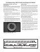
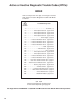
LED DIAGNOSTIC TROUBLE CODES
LFT ‑ Left
RHT ‑ Right
DRV ‑ Drive Axle
ADD ‑ Additional
STR ‑ Steer Axle
VLT ‑ Power
ECU ‑ ABS Controller
SEN ‑ Wheel Speed
Sensor
MOD ‑ Pressure Modulator
Valve
TRC ‑ Traction Control
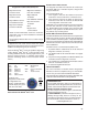
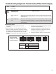
Example: If the
Diagnostic Trouble Code
is "Right Steer Axle
Sensor", the Bendix RDU
tool will display one green
and three red LEDs
LEDs
Green
VLT
Red
SEN
STR
RHT
FIGURE 20 - DIAGNOSTIC TROUBLE CODES AS
DISPLAYED ON THE BENDIX
®
RDU
™
TOOL
Bendix
®
RDU
™
Reset Function
The magnetic reset switch is located in the center top of
the Bendix RDU tool. Activation requires a magnet with
30 gauss minimum.
The reset operations are:
1. If the magnet is held over the switch for less than 6
seconds the "clear current DTCs" command is sent.
2. If the magnet is held over the switch for more than 6
seconds, but less than 30 seconds, the Bendix ABS
"self‑conguration command" is sent.
Additionally, it is recommended at the end of any inspection
that the user switches off and restores the power to
the Bendix ESP EC‑80 Controller, then check the ABS
Indicator Lamp operation and Bendix RDU tool to see if
they indicate any remaining DTCs.
Bendix RDU Communication Problems
If the Bendix ESP EC‑80 Controller does not respond to the
RDU tool’s request for DTCs, the RDU tool will illuminate
each red LED in a clockwise pattern. This pattern indicates
the loss of communication and will continue until the Bendix
ESP EC‑80 Controller responds and communication has
been established.
Possible sources of communication problems are:
1. A problem with the J1939 link at the in‑cab off‑board
diagnostic connector (9 or 6 Pin);
2. The Bendix ESP EC‑80 Controller does not support
PID194;
3. No power is being supplied to the Bendix ESP EC‑80
Controller and/or the diagnostic connector;
4. The J1939 bus is overloaded with information and the
RDU can not arbitrate access; or
5. A malfunctioning Bendix RDU tool.
Other Information
For more information on Bendix
®
ACom
®
Diagnostics
Software or RP‑1210 compliant tools, go to www.bendix.
com or visit your local authorized Bendix distributor.
See pages 56-62 for Appendices showing J1939 SID, FMI,
codes and their Bendix blink code equivalents.
www.bendix.com
For the latest information, and for free downloads of
the Bendix
®
ACom
®
Diagnostic Software, and its User
Guide, visit the Bendix website at www.bendix.com.
Bendix Technical Assistance Team
For direct telephone technical support, call the Bendix
technical assistance team at:
1-800-AIR-BRAKE (1‑800‑247‑2725 option 2, then 1),
Monday through Friday, 8:00 a.m. to 6:00 p.m. ET,
and follow the instructions in the recorded message.
E‑mail the Bendix Technical Assistance Team at:
techteam@bendix.com.