
User's Manual

24
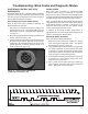
Troubleshooting: Using PC-Based or
Hand-Held Diagnostic Tools
BENDIX
®
ACOM
®
DIAGNOSTIC SOFTWARE
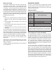
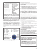
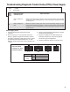
FIGURE 18 - BENDIX
®
ACOM
®
DIAGNOSTICS
Bendix
®
ACom
®
Diagnostic Software is a PC‑based
program and is designed to meet RP‑1210 industry
standards developed by the Truck Maintenance Council
(TMC). This software provides the technician with access
to all the available Bendix
®
EC‑80
™
ESP
®
Controller's
diagnostic information and configuration capability,
including:
• ECU information;
• Diagnostic Trouble Codes (DTCs) and repair
information;
• Conguration (ABS, ATC, and more);
• Wheel speed information;
• Perform component tests; and
• Save and print information
Note: Bendix ACom Diagnostic Software V6.7.2.5 (or
higher) is required to calibrate the Steering Angle
Sensor, the Yaw Rate/Lateral Acceleration Sensor, the
Brake Demand Sensors and the Load Sensor.
When using ACom Diagnostic Software V6.7.2.5 (or
higher) to diagnose the Bendix ESP EC‑80 Controller, the
computer’s serial or parallel port needs to be connected
to the vehicle’s diagnostic connector.
BENDIX
®
RDU
™
(REMOTE DIAGNOSTIC
UNIT)
The Bendix
®
RDU
™
tool (Bendix part number K101596N001)
provides the technician with a visual indication of Antilock
Braking System (ABS) component Diagnostic Trouble
Code (DTC) information. Note: Previous versions of the
RDU tool are not compatible with the Bendix ESP EC-80
Controller. The Bendix RDU tool is specically designed
for use with Bendix
®
brand ABS systems and Bendix makes
no claims for its operation and/or usability with other brands
of ABS systems.
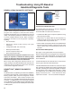
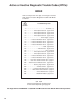
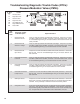
LED lights
illuminate
Diagnostic
Trouble
Codes
(10 locations
in total)
FIGURE 19 - THE BENDIX
®
REMOTE DIAGNOSTIC UNIT
Features of the Bendix RDU Tool
The Bendix RDU tool attaches to the 9‑pin diagnostic
connector in the cab of the vehicle.
The Bendix RDU tool allows the technician to:
• Troubleshoot ABS system component problems using
DTC reporting via LEDs;
• Reset DTCs on Bendix ESP EC‑80 Controllers by
holding a magnet over the reset in the center of the RDU
tool for less than six (6) seconds; and
• Enter the Self‑Conguration Mode used by Bendix ESP
EC‑80 Controllers by holding a magnet over the reset
area for greater than six (6) seconds but less than 30
seconds.
How the Bendix RDU Operates
See Figure 14 for typical vehicle connector locations.
When the Bendix RDU tool is plugged into the diagnostic
connector, all the LEDs will illuminate, and the green LED
will ash four (4) times to indicate communications have
been established.
If the Bendix ESP EC‑80 Controller has no active DTCs,
only the green LED will remain illuminated.
If the Bendix ESP EC‑80 Controller has at least one active
DTC, the RDU tool displays the rst DTC by illuminating the
red LEDs, indicating the malfunctioning ABS component
and its location on the vehicle (See Figure 20.) If there
are multiple DTCs on the ABS system, the RDU tool will
display one DTC rst, then — once that DTC has been
repaired and cleared — the next code will be displayed.