
User's Manual

23
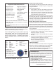
Inactive Diagnostic Trouble Code Mode
The Bendix
®
ESP
®
EC‑80
™
Controller stores past
Diagnostic Trouble Codes (DTCs) and comments (such
as conguration changes) in its memory. This record is
commonly referred to as “event history.” When an active
DTC is cleared, the Electronic Control Unit (ECU) stores it
in the event history memory as an inactive DTC.
Using blink codes, the technician may review all inactive
DTCs stored on the ECU. The ABS indicator lamp
will display inactive diagnostic blink codes when the
diagnostic Blink Code Switch is depressed and released
two times. See page 26 for the index showing DTCs and
the troubleshooting guide page to read.
Inactive DTCs, and event history, may be retrieved and
cleared by using a hand‑held or PC‑based diagnostic tool,
such as the Bendix
®
ACom
®
Diagnostic Software.
Clearing Active DTCs
The ECU will clear active DTCs when the diagnostic Blink
Code Switch is depressed and released three (3) times.
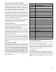
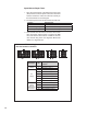
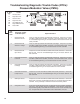
System Conguration Check Mode
The ABS indicator lamp will display system conguration
information when the diagnostic Blink Code Switch is
depressed and released four times. The lamp will blink
out conguration information codes using the following
patterns. (See Figure 17).
In this mode the ECU tells the technician — by means of a
series of seven (7) blink codes — the type of ABS system
that the ECU has been set up to expect. For example, if
the fourth blink code is the number two (2), the technician
knows that a 6S/4M sensor/modulator conguration has
been set.
Dynamometer Test Mode
The Dynamometer Test Mode is used to disable Bendix
®
ESP
®
& ATC system functions when needed (e.g. when
performing any vehicle maintenance where the wheels are
lifted off the ground and moving, including dynamometer
testing). Note: For Bendix ESP and ABS EC‑80
Controllers, this mode will remain engaged even if
power to the ECU is removed and re‑applied. To exit
the Dynamometer Test Mode, press and release the Blink
Code Switch three (3) times, or use a hand‑held or PC‑
based diagnostic tool.
1st Number System Power
1 12 Volts
2nd
Number
Wheel Speed Sensors
4 4 Sensors
6 6 Sensors
3rd Number Pressure Modulator Valves
4 4 Modulators
5 5 Modulators
6 6 Modulators
4th Number ABS Conguration
1 4S/4M or 6S/6M
2 6S/4M
3 6S/5M
5th Number Traction Control Conguration
2 No ATC
3 ATC Engine Control Only
4 ATC Brake Control Only
5 Full ATC (Engine Control & Brake Control)
6th Number Retarder Conguration
1 No Retarder
2 J1939 Retarder
3 Retarder Relay
4 J1939 Retarder, Retarder Relay
7th Number Stability Conguration
1 No Stability Program
2 Electronic Stability Program (ESP)
FIGURE 17 - SYSTEM CONFIGURATION CHECK
Recongure ECU Mode
Controller reconfiguration is carried out by using the
Recongure ECU Mode. (See page 16.)
Note: To enter the Reconguration Mode, the Blink Code
Switch must be held in before the application of ignition
power. Once the power is supplied, the switch is released
and then pressed seven times.
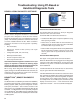
Other Methods
Troubleshooting and DTC clearing (as well as recongura‑
tion) may also be carried out using hand‑held or PC‑based
diagnostic tools such as the Bendix
®
Remote Diagnostic
Unit (RDU
™
), Bendix ACom Diagnostic Software, or similar
tools.