
User's Manual

22
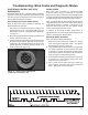
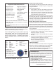
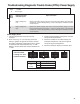
Blink Code Timing
The Bendix
®
ESP
®
EC‑80
™
Controller responds with
a sequence of blink codes. The overall blink code
response from the Electronic Control Unit (ECU) is called
a “message.” Each message includes, depending on the
mode selected by the technician, a sequence of one or
more groups of blinks. Simply record the number of blinks
for each sequence and then use the troubleshooting index
on page 26 for active or inactive Diagnostic Trouble Codes
(DTCs) and you will be directed to the page that provides
troubleshooting information.
NOTE:
1. Sequences of blinks illuminate the ABS indicator lamp
for half a second, with half‑second pauses between
them.
2. Pauses between blink code digits are one‑and‑a‑half
(1.5) seconds.
3. Pauses between blink code messages are two‑and‑a‑
half (2.5) seconds.
4. The lamp remains on for ve (5) seconds at the end of
messages.
Once the ABS indicator lamp begins displaying a sequence
of codes, it continues until all blink code messages have
been displayed and then returns to the normal operating
mode. During this time, the Bendix ESP EC‑80 Controller
will ignore any additional Blink Code Switch activation.
All DTCs, with the exception of voltage and J1939 DTCs,
will remain in an active state for the remainder of the
power cycle.
Voltage DTCs will clear automatically when the voltage
returns within the required limits. All Bendix ABS functions
will be re‑engaged.
J1939 DTCs will clear automatically when communications
are re‑established.
DIAGNOSTIC MODES
In order to communicate with the Bendix ESP EC‑80
Controller, there are several modes that the technician can
select to allow information to be retrieved, or other ECU
functions to be accessed.
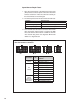
Diagnostic Modes
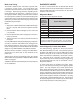
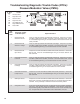
To enter the various diagnostic modes:
No. of
Times to
Press the
Blink Code
Switch
System Mode Entered
1 Active Diagnostic Trouble Code (DTC) Retrieval
2 Inactive DTC Retrieval
3 Clear Active DTCs
4 System Conguration Check
5 Dynamometer Test
7* Recongure ECU
* To enter the Reconguration Mode, the switch must be held
in before the application of ignition power. Once the power is
supplied, the switch is released and then pressed seven times.
FIGURE 16 - DIAGNOSTIC MODES
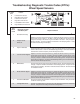
Active Diagnostic Trouble Code Mode
For troubleshooting, typically the Active and Inactive
DTC Retrieval Modes are used. The technician presses
the Blink Code Switch once and the ABS indicator lamp
ashes a rst group of two codes, and if there are more
DTCs recorded, this is followed by a second set of codes,
etc. (See page 26 for a directory of these codes.) All
active DTCs may also be retrieved using a hand‑held or
PC‑based diagnostic tool, such as the Bendix
®
ACom
®
Diagnostic Software.
To clear active DTCs (as problems are xed), simply
clear (or “self‑heal”) by removing and re‑applying ignition
power. The only exception is for wheel speed sensor
DTCs, which clear when power is removed, re‑applied, and
the ECU detects valid wheel speed from all wheel speed
sensors. Alternately, codes may be cleared by pressing the
diagnostic Blink Code Switch three (3) times (to enter the
Clear Active Diagnostic Trouble Code Mode) or by using
a hand‑held or PC‑based diagnostic tool. Hand‑held or
PC‑based diagnostic tools are able to clear wheel speed
sensor DTCs without the vehicle being driven.