
User's Manual

21
BLINK CODES
Blink codes allow a technician to troubleshoot ABS
problems without using a hand‑held or PC‑based
diagnostic tool. Instead, information about the ABS system
is communicated by the Bendix ESP EC‑80 Controller using
the ABS indicator lamp to display sequences of blinks.
Note: The Bendix ESP EC-80 Controller will not enter the
diagnostic blink code mode if the wheel speed sensors
show that the vehicle is in motion. If the ECU is in the
diagnostic blink code mode and then detects vehicle
motion, it will exit the blink code mode.
In addition, by operating the Blink Code Switch as
described below, one of several diagnostic modes can be
entered. See Diagnostic Modes below.
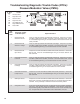
Blink Code Switch Activation
When activating the Blink Code Switch:
1. Wait at least two seconds after “ignition on.” (Except
when entering Reconguration Mode ‑ see System
Reconguration section on page 16.)
2. For the Bendix ESP EC‑80 Controller to recognize that
the switch is activated “on,” the technician must press
for at least 0.1 seconds, but less than ve (5) seconds.
(If the switch is held for more than ve (5) seconds, the
ECU will register a malfunctioning switch.)
3. Pauses between pressing the switch when a sequence
is required, (e.g. when changing mode) must not be
longer than two (2) seconds.
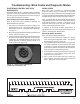
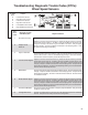
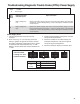
4. After a pause of three‑and‑a‑half (3.5) seconds, the
ECU will begin responding with output information
blinks. See Figure 15 for an example.
ELECTRONIC CONTROL UNIT (ECU)
DIAGNOSTICS
The Bendix
®
ESP
®
EC‑80
™
Controller contains self‑testing
diagnostic circuitry that continuously checks for the normal
operation of internal components and circuitry, as well as
external ABS components and wiring.
Active Diagnostic Trouble Codes (DTCs)
When an erroneous system condition is detected, the
Bendix ESP EC‑80 Controller:
1. Illuminates the appropriate indicator lamp(s) and
disengages part or all of the Bendix ABS, ATC and
ESP system functions. (See ABS Partial Shutdown,
on page 15.);
2. Places the appropriate DTC information in the Electronic
Control Unit (ECU) memory; and
3. Communicates the appropriate DTC information over
the serial communications diagnostic link as required.
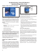
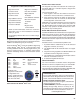
Hand‑held or PC‑based diagnostic tools attach to the
vehicle diagnostic connector, typically located on or
under the dash (see Figure 14).
FIGURE 14 - TYPICAL VEHICLE DIAGNOSTIC
CONNECTOR LOCATIONS (J1939)
Troubleshooting: Blink Codes and Diagnostic Modes
FIGURE 15 - EXAMPLE OF A BLINK CODE MESSAGE