
User's Manual
20
BRAKE DEMAND SENSOR CALIBRATION
Calibration must be performed under the following conditions:
• After servicing any pressure sensor related Diagnostic
Trouble Codes (DTCs)
• Replacement of any sensor
The calibration procedure is performed using Bendix
®
ACom
®
Diagnostic Software V6.7.2.5 (or higher).
See “Troubleshooting Diagnostic Trouble Codes: Brake
Demand Sensor/Load Sensor” for the calibration procedure.
PRESSURE SENSOR INSTALLATION
REQUIREMENTS
Service Checks:
1. Check all wiring and connectors. Make sure all
connections are free from visible damage.
2. Examine the sensor. Make sure the sensor and its
interface to the pressure location are not damaged.
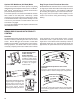
Diagnostics:
See the test diagram supplied by the Bendix ACom
Diagnostic Software. The pressure sensor can be
independently diagnosed when supplied with a ve volt
voltage supply to the B location and ground to the A
location shown in the test diagram. Signal output on
the C location should read approximately 0.5V if there is
no pressure applied. The signal output should increase
proportionately as pressure is applied, up to a maximum
of 4.5V at 150 psi.
Removal:
1. Unplug sensor cable assembly from body of sensor.
Pull gently on the mounting tab and connector until it
disengages.
2. Remove sensor from its pressure mounting using
approved air brake push in tting tools.
Installation:
1. Obtain a new sensor. The sensor is not repairable in
the eld.
2. Insert sensor into pressure tting using approved tools.
3. Reconnect the connector. Ensure that there will be no
force applied to the sensor because the connector is
pulling on the sensor body.
4. If the wire harness leading to the sensor is being
replaced, ensure that it is adequately tie wrapped.
Pressure Sensor Calibration:
There is no need for pressure sensor calibration as long
as the part replaced is identical to the part removed and a
component approved for use with the Bendix
®
ESP
®
system
with EC‑80
™
Controllers. However, replacement of brake
demand sensors or clearing of demand pressure sensor
related DTCs require the following:
1. Use Bendix ACom Diagnostic Software V6.7.2.5 (or
higher) to clear the active pressure sensor DTC.
2. Carrying out the demand pressure sensor initialization
procedure which involves applying service brakes of
90 psi or greater for three (3) seconds (while stationary).
Once this procedure is carried out successfully, if there are
no other active DTCs, the ATC/ESP indicator lamp will no
longer be illuminated.