
User's Manual

19
YAW RATE/LATERAL ACCELERATION
SENSOR MAINTENANCE
Different generations of yaw rate/lateral acceleration
sensors are not compatible. Only replace these
sensors with exactly the same device.
Service Checks:
1. Check all wiring and connectors. Make sure all
connections are free from visible damage.
2. Examine the sensor. Make sure the sensor, its
mounting bolts, and the mounting bracket are not
damaged.
3. Check the vent hole in underbody of sensor housing.
The vent hole should remain free from paint and debris
at all times.
Diagnostics:
The yaw rate sensor is only operational in conjunction with
a Bendix
®
ABS, ATC or ESP
®
system with the EC‑80
™
Controller. No independent diagnostics can be performed
on the sensor. See pages 40-41 for Diagnostic Trouble
Codes associated with this device.
Removal:
1. Unplug the sensor cable assembly from body of sensor.
The connector must be twisted and pulled gently to
release.
2. In some mounting congurations, the sensor can be
removed independently from its mounting bracket.
Otherwise, remove entire assembly, then remove
sensor from bracket.
3. Take note of the direction in which the connector is
pointed.
Installation:
1. Obtain a new sensor. The sensor is not repairable in
the eld.
The location of the Yaw Rate Sensor on the vehicle,
the means of fastening the unit to the vehicle, and
the sensor's orientation, MUST NOT BE ALTERED.
When servicing, an identical component must be
used in the same orientation (using OEM brackets
& torque requirements). During installation,
follow the OEM leveling guidelines. If any of these
requirements are not followed, the Bendix ESP
system may not function properly, which can result
in incidents leading to loss of vehicle control.
2. Assembly yaw rate sensor housing to mounting bracket.
The bracket must be the same design as used on the
original vehicle conguration.
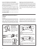
3. For Bendix
®
YAS‑60
™
Yaw Rate Sensors, the correct
fasteners are three M8 size bolts, and the xing torque
should be 20 Nm (±2 Nm). For Bendix
®
YAS‑70X
™
Yaw
Rate Sensors, the correct fasteners are two M10 size
bolts (1.5 mm pitch angle), or OEM‑supplied hardware,
and the xing torque should be 46 Nm (±9 Nm). Note
that the Bendix YAS‑70X sensor has two alternate
designs, one with an aligning post — see the kit
instruction sheet for more information. In all cases,
the connector should be facing in the same direction
as the removed sensor. The unit must not be installed
upside‑down where there is a pressure‑balancing hole.
4. The sensor should be as level as possible and parallel
to the road surface when installed on the vehicle.
5. Reconnect the connector. Ensure that there will be no
force applied to the sensor because the connector is
pulling on the sensor body.
When removing or installing the sensor, care must
be used to prevent damage. Do not strike or pry
the sensor. Do not use an impact tool to install the
mounting hardware.
Sensor Location Modications
The location and orientation of the Yaw Rate Sensor must
not be altered. When servicing, an identical component
must be used in the same orientation (using OEM brackets
& torque requirements). During installation follow the OEM
leveling guidelines.
Yaw Rate Sensor Calibration:
The yaw rate sensor calibration can only be achieved via
the Bendix ESP system with the EC‑80 Controller. The
sensor must be recalibrated after any of these situations:
• Replacement of the sensor
• After an accident that may have led to damage of the
yaw rate sensor
The calibration procedure is performed using Bendix
®
ACom
®
Diagnostic Software V6.7.2.5 or higher.
See “Troubleshooting Diagnostic Trouble Codes: Yaw Rate
Sensor” for the calibration procedure.