
User's Manual

9
PREVENTIVE MAINTENANCE
Every 3 months; 25,000 miles; or 900 operating hours;
1. Check all wiring and connectors to ensure they are
secure and free from visible damage.
2. Although the EC-16
™
controller incorporates self check
diagnostics, the LED display should be inspected to
ensure that it is functional. With the vehicle ignition on,
a magnet (800 gauss; capable of picking up 3 ounces)
held to the LED reset switch should cause all of the
LEDs to illuminate. If one or more of the LEDs DO NOT
ILLUMINATE and the dash condition lamps indicate
the system is functioning properly, the nonilluminated
LED(s) should be noted for future reference. Although
the diagnostic capabilities will be limited, the system
will continue to function as designed.
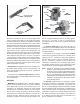
3. Road test the vehicle by making an antilock stop
from a vehicle speed of 20 miles per hour. When an
antilock stop is made, the modulator solenoids pulsate
and an audible burst of air can be heard from outside
of the cab. The wheels should not enter a prolonged
“lock” condition. Also, make a traction acceleration by
accelerating on a road surface with reduced traction. As
with antilock, audible bursts of air can be heard when
the traction system is functioning.
WARNING! PLEASE READ AND FOLLOW
THESE INSTRUCTIONS TO AVOID PERSONAL
INJURY OR DEATH:
When working on or around a vehicle, the following
general precautions should be observed at all times.
1. Park the vehicle on a level surface, apply the parking
brakes, and always block the wheels. Always wear
safety glasses.
2. Stop the engine and remove ignition key when
working under or around the vehicle. When working
in the engine compartment, the engine should be
shut off and the ignition key should be removed.
Where circumstances require that the engine be
in operation, EXTREME CAUTION should be used
to prevent personal injury resulting from contact
with moving, rotating, leaking, heated or electrically
charged components.
3. Do not attempt to install, remove, disassemble
or assemble a component until you have read
and thoroughly understand the recommended
procedures. Use only the proper tools and observe
all precautions pertaining to use of those tools.
4. If the work is being performed on the vehicle’s
air brake system, or any auxiliary pressurized air
systems, make certain to drain the air pressure
from all reservoirs before beginning ANY work
on the vehicle. If the vehicle is equipped with an
AD-IS
®
air dryer system or a dryer reservoir module,
be sure to drain the purge reservoir.
5. Following the vehicle manufacturer’s recommended
procedures, deactivate the electrical system in a
manner that safely removes all electrical power
from the vehicle.
6. Never exceed manufacturer’s recommended
pressures.
7. Never connect or disconnect a hose or line
containing pressure; it may whip. Never remove
a component or plug unless you are certain all
system pressure has been depleted.
8. Use only genuine Bendix
®
replacement parts,
components and kits. Replacement hardware,
tubing, hose, fi ttings, etc. must be of equivalent
size, type and strength as original equipment and
be designed specifi cally for such applications and
systems.
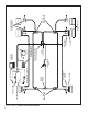
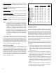
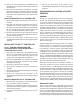
DIAGNOSTIC
DISPLAY LEDs
RESET SWITCH
FIGURE 7 - EC-16
™
CONTROLLER DIAGNOSTIC DISPLAY
9. Components with stripped threads or damaged
parts should be replaced rather than repaired. Do
not attempt repairs requiring machining or welding
unless specifi cally stated and approved by the
vehicle and component manufacturer.
10. Prior to returning the vehicle to service, make
certain all components and systems are restored
to their proper operating condition.
11. For vehicles with Antilock Traction Control (ATC),
the ATC function must be disabled (ATC indication
lamp should be ON) prior to performing any vehicle
maintenance where one or more wheels on a drive
axle are lifted off the ground and moving.
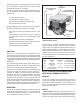
REMOVING THE EC-16
™
CONTROLLER
EC-16
™
CONTROLLER MOUNTED ON
ANTILOCK RELAY VALVE OR ANTILOCK
TRACTION RELAY VALVE
1. Identify and remove all air lines connected to the unit.
2. Disconnect the electrical connector(s) from the EC-16
™
controller.
3. Note and mark the mounting position of the assembly
on the vehicle. Loosen, remove and save the nuts on
the mounting hardware that attaches the controller
relay assembly bracket to the vehicle. Remove the
relay valve and EC-16
™
controller from the vehicle.