
User's Manual

8
Mid or rear sensor - Antilock on that wheel is disabled,
but antilock on all other wheels remains active. Traction
control is disabled.
Controller - Antilock and traction are disabled. The system
reverts to standard air braking.
Traction solenoid - Traction control is disabled. Antilock
remains active.
Engine Control Module* - If the engine control module
(ECM) or the wiring from the EC-16
™
controller to the ECM
fails, traction control is disabled. Antilock remains active.
Voltage* - If system voltage is out of range, antilock and
traction are disabled. The system reverts to standard air
braking.
*Note: A voltage problem and an intermittent ECM wiring
problem can “correct” themselves. For example,
a power surge can take the system out of voltage
range for a moment, which will fl ash the voltage
LED and an intermittent wiring problem between
the EC-16
™
controller and the ECM can cause
the traction LED to go on. During the time that the
problem is occurring, the dash lamp will also be
on. When the problem corrects itself, the system
is restored. The dash lamp and the appropriate
LED go out.
For all other problems, the system will not be restored
in the problem area until the error is corrected and the
EC-16
™
controller is cleared with the reset switch. It should
be remembered that the driver will be advised of the
degraded operation via the dash lamps and that standard
air braking will still be available on those brakes where the
EC-16
™
controller has disabled the system.
MULTIPLE FAILURES
In the event that multiple failures occur, the dash lamp will
react as it normally would during a single failure, and the
LEDs will show one failure at a time. When the fi rst problem
is fi xed and the system is reset, the next problem area
will appear at the LEDs. This way, the driver or mechanic
does not lose track of problem areas, and the system is
not restored until each and every error is corrected and the
EC-16
™
controller is reset.
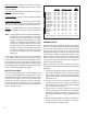
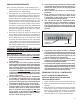
SYSTEM STILL OPERATING (YES/NO)
Std.
ABS Front ABS Rear Traction Braking
Left Right Left Right
RF Sensor YES YES YES YES NO YES
LF Sensor YES YES YES YES NO YES
RM Sensor YES YES YES YES NO YES
LM Sensor YES YES YES YES NO YES
RR Sensor YES YES YES NO NO YES
LR Sensor YES YES NO YES NO YES
RF Modulator YES NO YES YES YES YES
LF Modulator NO YES YES YES YES YES
RR Modulator YES YES YES NO NO YES
LR Modulator YES YES NO YES NO YES
Controller NO NO NO NO NO YES
Solenoid YES YES YES YES NO YES
Engine Control YES YES YES YES NO YES
Module*
Voltage* NO NO NO NO NO YES
*When ECM wiring or voltage “corrects” itself, system is restored.
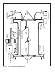
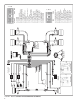
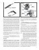
ANTILOCK AND TRACTION WIRING
GENERAL NOTES
The wires that carry information and power into and out of
the EC-16
™
controller are generally grouped and terminate
at a connector. The wire groups or wire harnesses along
with the connectors are most often specified and/or
supplied by the vehicle manufacturer. The connectors used
on the EC-16
™
controller are illustrated in Figure 4. The
wiring harnesses and connectors are weather resistant
and the wires that enter the connector are sealed to the
connector. The wire gauge used in the wire harnesses is
specifi c to the task performed.
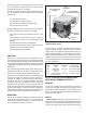
When diagnosing wiring in the antilock system the
following general rules apply and should be followed where
applicable:
1. It is generally advisable to replace a wire harness rather
than repair individual wires in the harness. If a splice
repair must be made, it is important that the splice be
properly soldered with a rosin fl ux (not acid based) and
made water proof.
2. Do not pierce wire insulation when checking for
continuity. Check for power, ground or continuity by
disconnecting the connector and testing the individual
pins or sockets in the connector.
3. Always check the vehicle handbook for wire and
connector identifi cation. Individual wire identifi cation
will differ depending upon the type of connectors in use,
the vehicle manufacturer, and the system features in
use.
4. While the retarder disable, serial link, and traction on/
off connections (4 total) are present on all EC-16
™
controllers they are not always used.
FAILURE LOCATION