
User's Manual
6
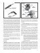
If the EC-16
™
controller is programmed for traction control,
it contains the following outputs:
- A connection to the engine’s electronic control module
allows the EC-16
™
controller to reduce engine torque under
certain circumstances.
- A traction dash light is connected to and controlled by
the EC-16
™
controller and serves as a means of advising
the driver of the condition of the traction control system.
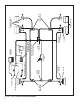
- A connection to the traction solenoid (located in the
upper portion of the antilock traction relay valve—see
Figure 3) is provided via a 2 pin Deutsch connector.
OPERATION - ANTILOCK
PHILOSOPHY
The Bendix
®
EC-16
™
controller antilock system uses
individual sensors, modulators and an electronic controller
to control the four vehicle wheel ends. By monitoring
the deceleration rate during braking, and subsequently
adjusting the brake application pressure at each wheel, the
EC-16
™
controller is able to improve braking between the
vehicle tire and the road surface it is on, while maintaining
vehicle stability.
The rear axle brakes are controlled independently;
therefore brake application pressure at an individual wheel
is adjusted solely on the basis of its behavior on the road
surface on which it is traveling.
While each steering axle brake is under the control of an
individual modulator, the EC-16
™
controller does not treat
these brakes totally independently. The EC-16
™
controller
uses a modified individual control philosophy for the
steering axle brakes. This is done in order to minimize
“steering wheel pull” in the event each wheel is traveling on
a different road surface (for example, ice close to the curb
and a dry crown). Essentially the EC-16
™
controller controls
the braking force differences between the two brakes.
The wheel on dry pavement is initially given less braking
force and is brought up to optimum during the stop, while
the wheel on ice attempts to maintain optimum braking
during the entire stop.
In the case of vehicles equipped with tandem rear axles
(6x2, 6x4), the wheel speed sensors are installed at the
wheels on the axle that is most likely to lock fi rst. A single
modulator controls both curb side brakes on the tandem,
and another modulator controls both brakes on the driver’s
side of the tandem. With this arrangement of speed sensors
and modulators, both brakes on one side of the tandem are
treated as one since they will most likely be on the same
type of road surface.
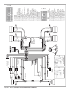
NON ANTILOCK BRAKE APPLICATION
During normal braking, air pressure from the brake valve
enters the control port of the service relay valve. The
service relay delivers air to, and through, the antilock
modulator located near the braked wheel, and into the
brake actuator. The service brakes are thus applied. If the
wheel sensors do not detect an impending wheel lock up,
the EC-16
™
controller does not initiate any corrective action
and the vehicle comes to a stop in a normal fashion.
ANTILOCK BRAKE APPLICATION
If a service brake application is made and the wheel speed
sensors detect an impending wheel lockup, the EC-16
™
controller will immediately begin modifi cation of the brake
application using the antilock modulator(s) at the affected
wheel(s). Solenoid valves contained in the modulator are
energized and de energized by the EC-16
™
controller in
order to modify the brake application. When a solenoid
coil is energized, its shuttle moves. Depending upon the
function of the specifi c solenoid, it either opens or closes,
thereby causing the exhaust or re application of air pressure
to the brake actuator. The solenoids in each modulator
are controlled independently by the EC-16
™
controller. By
opening and closing the solenoid valves in the appropriate
modulator, the EC-16
™
controller is actually simulating
what drivers do when they “pump the brakes”. It must be
remembered however that unlike the driver, the EC-16
™
controller is able to “pump” each brake on the vehicle
independently and with far greater speed and accuracy.
OPERATION - TRACTION CONTROL
PHILOSOPHY
Traction control is a natural extension of antilock. Just as
antilock helps vehicle control and stability during braking,
traction control helps during vehicle acceleration. The
wheel speed sensors not only detect rapid decreases in
wheel speed for antilock but also detect unreasonably
high increases for traction control. With traction control,
a spinning wheel is instantly detected and compared with
the other wheels on the vehicle, both front and rear. Two
different methods are used to control wheel spin; torque
limiting and differential braking. Depending upon vehicle
type, speed and road (surface) condition, each method
provides a unique and desirable type of wheel spin control.
Ideally both methods are used to control vehicle traction.
While all new version EC-16
™
controllers are capable
of providing wheel control antilock and traction control
(utilizing both methods of control), not all systems will be
confi gured for both methods. Depending upon the vehicle,
either or both traction control methods will be activated
during the self confi guration procedure.