
User's Manual

5
the EC-16
™
controller in the form of an AC signal which
varies in voltage and frequency as the speed of the wheel
increases or decreases. The EC-16
™
controller is designed
to receive wheel speed information, from various wheel
speed sensor models, at the rate of 100 pulses per wheel
revolution. The EC-16
™
controller is able to simultaneously
receive, and individually interpret, speed signals from six
wheel speed sensors. Vehicle drive confi guration and
whether the traction control feature is in use determines
the number of speed sensors that must be used. A vehicle
with a single rear axle drive (4 x 2, 4 x 4 or 6 x 2) requires
4 speed sensors for both antilock and traction operation.
A vehicle with two rear drive axles (6 x 4) requires 4 speed
sensors for antilock only operation, but have the option to
use 6 speed sensors for enhanced performance of both
antilock and traction operation.
- Vehicle power is supplied to the EC-16
™
controller from
the ignition switch through a fuse or circuit breaker. (30
amp.) The electrical ground for the EC-16
™
controller is
the vehicle chassis.
- A connection for a traction enable switch is provided,
but not always used. The switch allows traction to be turned
on or off manually.
OUTPUTS
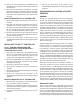
- Modulators, like the Bendix
®
M-21
™
or M-22
™
modulator,
are the means by which the EC-16
™
controller modifi es
driver applied air pressure to the service brakes. The
modulator is an electrically controlled air valve located
near the service actuator(s) it controls. It is the last valve
that air passes through on its way to the brake actuator.
A wiring harness connects the modulator to the EC-16
™
antilock controller. Solenoid valves contained in the
modulator provide the electrical interface between the
EC-16
™
controller electronics and the air brake system.
The EC-16
™
controller is able to simultaneously
and independently control four individual modulator
assemblies.
- An antilock dash light and its electrical relay are
connected to, and controlled by, the EC-16
™
controller and
serve as a means of advising the driver of the condition of
the antilock system.
- A connection to the engine or transmission retarder
and its relay is provided on the EC-16
™
controller, which
allows the EC-16
™
controller to temporarily disable the
retarder during certain modes of operation. While the
EC-16
™
controller is capable of this function, and
connections are provided, it is not always used. Use of
the retarder disable function is not essential but highly
recommended for vehicles equipped with a retarder.
Note: The EC-16
™
controller can also disable the retarder
using the same J1922 protocol it uses to control
the traction control, engine torque limiting feature.
For this redundant retarder disable to function, the
EC-16
™
controller must be connected to the engine
control module (as would be the case if the EC-16
™
controller is programmed for the traction control,
torque limiting feature).
- The data link enables the EC-16
™
controller to “report”
its operating condition to a specialized, external computer
in response to certain commands it receives. The
EC-16
™
controller diagnostic data link hardware conforms
to S.A.E. standard J1708. The protocol, or coded language
used, conforms to S.A.E. standard J1587. There are two
connections to the EC-16
™
controller devoted to the data
link. While connections are provided for this function, it
is not always used. The data link is not essential for the
EC-16
™
controller to be functional.
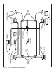
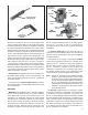
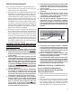
WS-20
™
STRAIGHT
SPEED SENSOR
WS-20
™
90
DEGREE SPEED
SENSOR
FIGURE 5 - WS-20
™
SPEED SENSORS
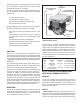
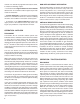
ELECTRICAL
CONNECTOR
DELIVERY
PORT
SUPPLY
PORT
EXHAUST
PORT
SUPPLY
PORT
DELIVERY
PORT
ELECTRICAL
CONNECTOR
M-21
™
MODULATOR
EXHAUST
PORT
M-22
™
MODULATOR
FIGURE 6 - MODULATORS