
User's Manual
13
6. All or part of traction control can be lost during self
confi guration by;
A. Not connecting one of the wire harnesses (engine
control module for torque limiting and ATR valve
solenoid for differential braking)
B. A missing or inoperative traction dash lamp (bulb
missing or burned out).
C. A missing or inoperative traction control enable
disable switch.
D. Not placing the traction control enable / disable
switch in the disabled position. The operator can
tell that the traction features are lost by noting the
absence of the traction lamp fl ash upon power up.
The operator should note the fl ashing of the antilock
condition lamp, and the traction lamp if traction
equipped, upon every power up. Observing the
dash lamps is the only method the operator has to
verify the system operation.
7. The EC-16
™
controller can be reprogrammed up to
10,000 times.
8. When a replacement EC-16
™
controller is installed on
a vehicle that does not have one or more of the pre-
programmed features, a failure will be registered on the
dash lamp(s) and on the EC-16
™
controller diagnostic
display. For this reason it is necessary to perform the
self confi guring procedure.
9. Some configuration information is available by
observing the reaction of the dash condition lamps on
vehicles confi gured with traction control and equipped
with the self confi guring EC-16
™
controller. When the
ignition is switched ON, the EC-16
™
controller self test
is begun. During the self test the dash lamps will fl ash
on and off together as indicated in the chart, depending
upon the type and amount of traction control confi gured
into the EC-16
™
controller. Note: For more information
on this subject see the TROUBLESHOOTING section
of this document.
Self Confi guration Process
In order to successfully complete the self confi guring
process follow the steps presented.
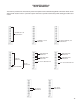
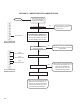
1. Connect all antilock and traction control wire harnesses.
Refer to the schematic in Figure 4. Make certain that
all the speed sensors present on the vehicle are
connected (H2, H3, J1, J2 on the 30 pin connector
and E2, E3, F2, F3, B2, B3, C2, C3 on the 18 pin
connector). If the vehicle has an electronic engine and
traction control torque limiting is desired the engine
control module must be connected (B2 and B3 on the
30 pin connector). If the vehicle is equipped with either
an ATR-1
™
or ATR-2
™
valve, the solenoid connection
must be made to the EC-16
™
controller (D2 and D3 on
the 18 pin connector) in order to obtain traction control
differential braking.
2. If the vehicle is to be confi gured with traction control, it
must have a traction control dash lamp and a traction
control enable / disable switch. Both the lamp and
switch must be functional. Place the traction control
enable/disable switch in the traction control disabled
position (traction control inoperative).
3. Turn the ignition ON and hold a magnet on the RESET
position of the EC-16
™
controller diagnostic display
until the LEDs begin to randomly fl ash then remove
the magnet. If the magnet is not removed during the
random LED fl ashing a second self confi guration may
be initiated. The magnet may have to be held on the
RESET for as long as 20 seconds. When the self
confi guration process is complete the EC-16
™
controller
will automatically go through a self test. During the
self test the diagnostic display will indicate the new
confi guration as described under the section entitled
EC-16
™
Controller Confi guration Display. Note: If the
EC-16
™
controller is being confi gured with traction
control (either torque limiting, differential braking or
both), the traction control condition dash lamp, will
be illuminated as well as the appropriate LEDs on the
EC-16
™
controller diagnostic display. The traction
control dash lamp will be illuminated until the traction
control enable / disable switch is placed in the traction
control enabled position (traction control operative).
4. Place the traction control enable / disable switch in
the traction control enabled position (traction control
operative), the traction control dash lamp should be
off.
5. Before placing the vehicle in service, verify the
configuration and the system condition by turning
the ignition OFF then ON while observing the
EC-16
™
controller diagnostic display. The diagnostic
display should indicate the desired confi guration as
described under the section entitled EC-16
™
Controller
Confi guration Display and no red LEDs should be
illuminated at the end of the self test.
6. If the confi guration appears correct but the diagnostic
LEDs indicate a failure somewhere in the system, refer
to the General Confi guration Information below and use
the Troubleshooting section of this manual to locate and
repair the problem.
7. If the confi guration is incorrect, the process can be
repeated as required. One common error is performing
the self confi guration with the traction enable / disable
switch in the wrong position. This will prevent any
traction features from being activated. Note: The
traction switch must be in the disable position to
confi gure traction, but must be placed in the enable
position to allow the traction lamp to fl ash.