
User's Manual

6
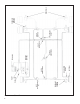
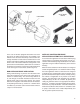
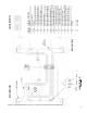
FIGURE 5 - M-21
™
MODULATOR
SOLENOID
CONNECTOR
EXHAUST
SUPPLY
MOUNTING
HOLES
DELIVERY
SUPPLY
ANTILOCK SYSTEM OPERATION -
COMPONENT FAILURE
The Bendix
®
EC-15
™
controller handles equipment failure
using a conservative fail-safe philosophy. Any single
electrical failure of a component devoted to antilock
braking, results in simultaneous illumination of the antilock
condition lamp on the dash, a disabling of all or part of
the antilock system, and reversion to standard braking on
wheels no longer under the control of antilock. When coping
with wheel equipment (modulator or wheel speed sensor/
exciter) failure, the EC-15
™
controller divides and separates
the brakes diagonally. For example; if the modulator at
the right front wheel has a broken wire lead, the EC-15
™
controller disables the antilock function for BOTH the right
front and left rear wheels. The antilock will continue to
function on the left front and right rear wheels and will
remain under the control of the EC-15
™
controller. (Note:
Right and left, front and rear are determined from the
driver’s seat. Left front is therefore the corner closest to the
driver). Depending upon the type of failure and its position
of occurrence the EC-15
™
controller either disables all, or
only a portion, of the antilock system. A power or controller
failure, for instance, will result in complete disabling of the
antilock system and reversion to standard braking on all
wheels. Two or more failures, regardless of their position
of occurrence, will also result in the disabling of the entire
system. With the failed component approach described,
the vehicle will retain improved braking stability after a
single failure. It should be remembered that the driver will
be advised of the degraded antilock operation via the dash
lamp and that standard air braking will still be available on
those brakes where the antilock has been disabled by the
EC-15
™
controller.
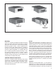
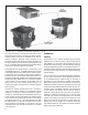
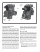
ANTILOCK WIRING
The wires that carry information and power into and out of
the EC-15
™
controller are generally grouped and terminate
at a connector. The wire groups or wire harnesses along
with the connectors are most often specified and or
supplied by the vehicle manufacturer. Two examples of the
connectors used on the EC-15
™
controller are illustrated
in fi gures 7 & 8. The wiring harnesses and connectors are
weather proof and the wires that enter the connector are
sealed to the connector. The wire gauge used in the wire
harnesses is specifi c to the task performed.
When diagnosing wiring in the antilock system the
following general rules apply and should be followed where
applicable:
1. It is generally advisable to replace a wire harness rather
than repair individual wires in the harness. If a splice
repair must be made, it is important that the splice be
properly soldered with a rosin fl ux (not acid based fl ux)
and made water proof.