
User's Manual

4
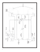
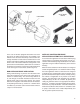
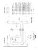
FIGURE 4 - EC-15
™
CONTROLLER MOUNTED ON AN AR-1
™
VALVE
EC-15
™
ELECTRONIC
CONTROLLER
AR-1
™
ANTILOCK
RELAY VALVE
the service actuator(s) it controls and is the last air valve
through which air passes on its way to the brake actuator.
A wiring harness connects the modulator to the EC-15
™
antilock controller. Solenoid valves contained in the
modulator provide the electrical interface between the
EC-15
™
controller electronics and the air brake system. The
EC-15
™
controller is able to simultaneous and independently
control four individual modulator assemblies.
A dash light and its electrical relay is connected to, and
controlled by, the EC-15
™
controller and serves as a means
of advising the driver of the condition of the antilock system.
A connection to the engine or transmission retarder is
provided on the EC-15
™
controller which allows the EC-15
™
controller to temporarily “disable” the retarder during certain
modes of operation. While the EC-15
™
controller is capable
of this function, and connections are provided, it is not
always used. Use of the retarder disable function is not
essential but highly recommended for vehicles equipped
with a retarder.
The data link function enables the EC-15
™
controller to
“report” its operating condition to a specialized, external
computer in response to certain commands it receives.
The EC-15
™
controller data link confi guration conforms to
S.A.E. standard J1708 and the protocol, or coded language
used, conforms to S.A.E. standard J1587. There are two
connections to the EC-15
™
controller devoted to the data
link. While the EC-15
™
controller is capable of this function,
and connections are provided, it is not always used. Use
of the data link is not essential for the EC-15
™
controller
to be functional.
OPERATION
GENERAL
The Bendix
®
EC-15
™
antilock controller system provides
individual wheel control by using a wheel speed sensor
and modulator at each wheel. By monitoring the rate of
deceleration during braking, and subsequently adjusting
the brake application pressure at each wheel, the EC-15
™
controller is able to provide improved braking between the
vehicle tire and the road surface it is on, while maintaining
vehicle stability.
The rear axle brakes are controlled completely independent
of each other and therefore brake application pressure
at an individual wheel is adjusted solely on the basis of
its behavior on the road surface on which it is traveling.
While each steering axle brake is under the control of an
individual modulator, the EC-15
™
controller does not treat
these brakes totally independent of each other. The EC-15
™
controller utilizes a modifi ed individual control philosophy
for the steering axle brakes. This is done in order to
minimize “steering wheel pull” in the event each wheel is
traveling on a different road surface (e.g.; ice close to the
curb and a dry crown). Essentially the EC-15
™
controller
controls the braking force differences between the two
brakes. The wheel on dry pavement is initially given less
braking force and is brought up to optimum during the
stop, while the wheel on ice attempts to maintain optimum
braking during the entire stop.