
User's Manual
12
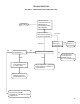
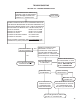
TROUBLESHOOTING
GENERAL
While the EC-15
™
controller diagnostic display locates
a specifi c problem area, it is still necessary to confi rm
whether the problem resides in the component itself or the
wiring. Basically the troubleshooting procedure that follows
is devoted to narrowing the problem to either the wiring or
a specifi c antilock component.
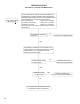
TROUBLESHOOTING TIPS
1. All troubleshooting begins by observing the antilock
condition lamp on the dash. Troubleshooting should
begin by fi rst performing the “Initial Start-up Procedure”
and following the directions contains in it.
2. The troubleshooting technician should record all
fi ndings and the action taken during the troubleshooting
process.
3. No voltage or resistance tests are performed into the
EC-15
™
controller. All voltage and resistance tests
are performed by beginning at the wire harness half
of the connector and moving AWAY from the EC-15
™
controller toward an antilock system component
(modulator, wheel speed sensor, etc.)