
User's Manual
10
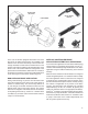
not to damage the gasket between the two components.
Peel the gasket from the EC-15
™
controller or antilock
relay valve and retain for reuse. Note: Use a new
gasket if damaged during removal or if a new gasket
is immediately available.
BRACKET MOUNTED EC-15
™
CONTROLLER
1. Disconnect the electrical connector(s) from the EC-15
™
controller.
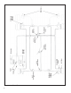
2. Note and mark the mounting position of the EC-15
™
controller on the vehicle. Loosen, remove and save
the nuts on the mounting hardware that attaches the
EC-15
™
controller bracket to the vehicle. Remove the
EC-15
™
controller and bracket from the vehicle.
3. Remove and retain the four cap screws that secure the
EC-15
™
controller to the bracket. Separate the EC-15
™
controller from the bracket.
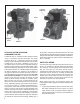
INSTALLING THE EC-15
™
CONTROLLER
ASSEMBLY
EC-15
™
CONTROLLER MOUNTED ON ANTILOCK
RELAY VALVE
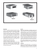
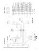
1. After noting the relationship of the positioning marks
made prior to disassembly, position the gasket on the
EC-15
™
controller then secure the EC-15
™
controller
to the antilock relay valve using the four cap screws.
Torque the cap screws to 50-80 lbs. in.
2. Mount the assembled EC-15
™
controller and antilock
relay valve on the vehicle and orient it in the position
marked prior to removal.
3. Reconnect all air lines to the assembly.
4. Reconnect the electrical connector(s) to the EC-15
™
controller.
5. Test the antilock relay valve for operation and leakage
prior to placing the vehicle in service.
6. Perform the “Initial Start-up Procedure” in the
TROUBLESHOOTING section to assure proper
antilock system operation.
BRACKET MOUNTED EC-15
™
CONTROLLER
1. Secure the EC-15
™
controller to its bracket using the
four cap screws. Torque the cap screws to 50-80 lbs.
in.
2. After noting the positioning marks, mount the EC-15
™
controller on the vehicle using the mounting hardware
retained during removal.
3. Connect the electrical connector(s) to the EC-15
™
controller.
4. Perform the “Initial Start-up Procedure” in the
TROUBLESHOOTING section to assure proper
antilock system operation.
DIAGNOSING AND LOCATING A SYSTEM
PROBLEM
GENERAL
The EC-15
™
controller contains self test and diagnostic
circuitry that continuously checks for proper operation of
the entire antilock system including wiring continuity. A dash
lamp, controlled by the EC-15
™
controller, advises the driver
of the condition of the entire antilock system. The condition
of specifi c antilock components is provided to the mechanic
by a series of labeled, light emitting diodes (LED’s)
displayed through a “window” in the EC-15
™
controller
housing. No special tools or equipment are needed to read
or interpret the EC-15
™
controller diagnostics window. It
should be noted that the EC-15
™
controller diagnostics
display is separate from the antilock condition lamp on
the dash. With this separation, the driver is aware of any
problems that occur but is not confused by the diagnostic
information. A special feature of the EC-15
™
controller is
the failure latching and diagnostic system. Intermittent
problems, particularly in the wheel speed sensing area
can be diffi cult to diagnose. When the controller senses an
erroneous condition, whether in the controller electronics,
the modulator or wheel speed sensing areas, it stores the
condition in non-volatile memory, disables the antilock
function, illuminates the dash mounted antilock condition
lamp and the appropriate diagnostic LEDs on the EC-15
™
controller.
The failure condition is truly stored and is not cleared
by loss of power to the EC-15
™
controller. The LEDs will
re-light when power is restored and remain illuminated
until the failure is corrected. After the actual problem is
corrected, maintenance personnel can clear or reset the
EC-15
™
controller diagnostics by passing a small magnet
over the RESET point in the diagnostics window.
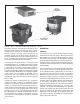
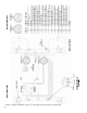
DIAGNOSTIC LEDs
There are nine LEDs plus a magnetically actuated reset
switch in the EC-15
™
controller diagnostic window. The
fi rst fi ve LEDs locate a problem to a specifi c area of the
vehicle while the last four indicate the problem component
or its wiring. The LEDs are software driven and are either
ON or OFF depending upon their monitor function. (Note:
Right and left, front and rear are determined from the
driver’s seat. Left front is therefore the corner closest to
the driver.)