
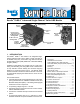
User's Manual

7
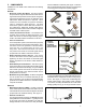
6. MOUNTING CONFIGURATIONS
Tank (Nipple) Mount
The TABS‑6 Advanced module can be tank‑mounted using
aschedule80(heavygaugesteel)3/4”NPTnippledirectly
between the trailer supply tank and the module’s supply
port. A tank with a reinforced port must be used.
Frame (Chassis) Mount
The TABS‑6 Advanced module provides through‑holes for
frame mounting directly to the trailer frame rail or cross‑
member. It is recommended to use two Grade 5
3
/8‑16 bolts,
typicallength5”,torquedto180-220in-lbs.
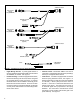
7. PIGTAIL WIRING HARNESSES
Several pigtail wire harnesses are available to connect
the TABS‑6 Advanced module with ABS and other trailer
system components. Pigtail harness are weather sealed
at the connector interface and are clearly labeled for
proper installation. Because of the over‑molded design of
the TABS‑6 Advanced module wiring harnesses, Bendix
recommends that the complete harness be replaced if
damage or corrosion occurs.
TABS‑6 Advanced modules include the two primary wheel
speed sensor connections and therefore these are separate
from the pigtail harness.
ECU Connectors
TABS-6AdvancedmoduleECUconnectorsusean18-pin
DeutschDTseriesconnectorforbrakelightpower,constant
power, ground, the trailer‑mounted ABS indicator lamp and
auxiliaryI/O’s.
Power/ABS Indicator Lamp Connector
The TABS‑6 Advanced module pigtail uses a TTMA
RP 7‑99 5‑pin Packard Weather Pack connector for brake
light power, constant power, ground and the trailer‑mounted
ABS indicator lamp.
The Power/ABS indicator lamp lead of the pigtail harness
is available in several lengths to satisfy most installation
requirements(e.g.slideraxles).
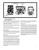
SAE J1939 (CAN) Connector
See Figure 6.
TABS‑6 Advanced module pigtail harnesses provide a 4‑pin
connectionforvariousECUcommunications.Typicaluses
includeJ1939diagnostics,andconnectiontotheBendix
®
Trailer Information Module.
Auxiliary I/O Connector
The TABS‑6 Adv module pigtails provide an option for up
tofourauxiliaryI/Osandtwoactivesensorinputs.
Examplesofusesoftheauxiliaryconnectorare:
• Liftaxlesensing.
• Rear axle suspension air bag dump.
• Automatic lift axle control.
• Externalspringdeectionsensorformechanicalspring
suspensions.
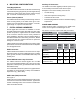
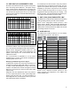
POWER AND GROUND
Trailer electrical power is supplied to the TABS‑6 Adv
module from the ignition and brake light circuits.
See Charts 1 and 2 for output values and pin locations.
Function Mode Value
OperatingRange 8.0to32.0VDC
ECUActive 150mA@12VDC
ABS Active 2.0A@12VDC
CHART 1 – VALUES FOR OUTPUTS
Circuit
7‑Pin
Trailer
Conn.
5‑Pin
ABS
Conn.
18‑Pin
ECU
Conn.
IgnitionPowerPLC
(Blue Wire)
7 B 6
BrakeLightPower
(Red Wire)
4 A 12
Ground
(White Wire)
1 E 18
IndicatorLamp
(White/Green Wire)
N/A D 5
CHART 2 – POWER AND GROUND